09/03
4-21
DC 3535/2240/1632, WC M24
REP 4.4
Repairs and Adjustments
Initial issue
REP 4.4 Drum Motor Assembly
Parts List on PL 1.1
Removal
WARNING
To avoid personal injury or shock, do not perform repair or adjustment activities with
the power switch on or electrical power applied to the machine.
CAUTION
Machine problems will result from careless harness routing during reassembly. Carefully
observe position of wiring harnesses for later reinstallation.
1. Remove the 24 VDC LVPS Chassis (REP 1.9).
2. Remove the Right Cover (REP 14.3).
3. Remove the Top Cover (REP 14.1).
4. Remove the Rear Cover (REP 14.2).
5. Remove the ESS DIMM cover (PL 13.1, item 4).
6. Disconnect J300 (DC2240/1632) or NJ300 (DC3535) from the ESS PWB.
CAUTION
Disengage locking tab on P/J400 before disconnecting.
CAUTION
PWBs can be damaged by electrostatic discharge. Observe all ESD procedures.
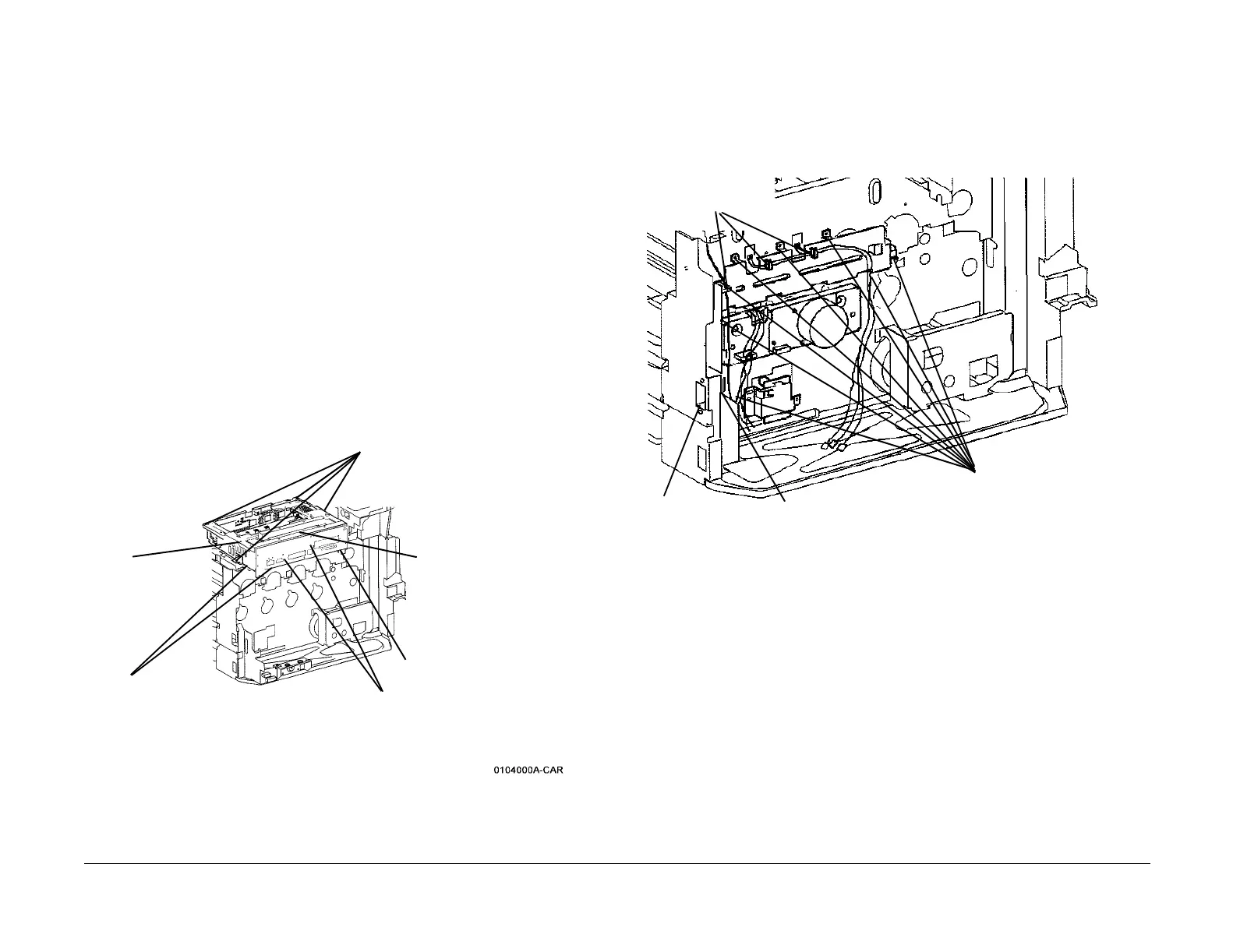
7. Remove the ESS Chassis Assembly (Figure 1).
Figure 1 Removing ESS Chassis
8. Remove the High Voltage Power Supply Chassis (REP 1.6).
NOTE: In next step, do not disconnect connectors.
9. Loosen the I/F PWB chassis mounting screws (2) and move chassis up (REP 1.8).
10. Remove the IBT Motor Assembly (REP 4.2).
11. Remove the BTR1 HVPS (REP 1.10).
12. Remove the LVPS Bracket (REP 1.1).
13. Remove the Drum Motor Assembly (Figure 2).
Figure 2 Removing Drum Motor Assembly
4
Remove screws (4)
1
Unlatch Harness Clips
(2)
3
Disconnect
Switch from
chassis
2
Disconnect connectors (8) from MCU PWB
(under chassis)
5
Lift outer end of chas-
sis to disconnect P/
J410 and remove
chassis
P/J400 (see CAUTION)
Release Harness Clips
2
Remove screws
(2)
3
Disconnect connector
4
Remove screws (8)
 Loading...


