09/03
2-292
DC 3535/2240/1632, WC M24
12-916
Initial issue
Status Indicator RAPs
12-916 Stapling
The Staple Head Home Sensor turned on by the open operation while the Sensor failed to turn
on (stapling was not available due to an error) after the Staple Head began to close.
Procedure
Position paper in stapler. Enter dC330 [012-020] and press Start. The Staple Motor ener-
gizes.
YN
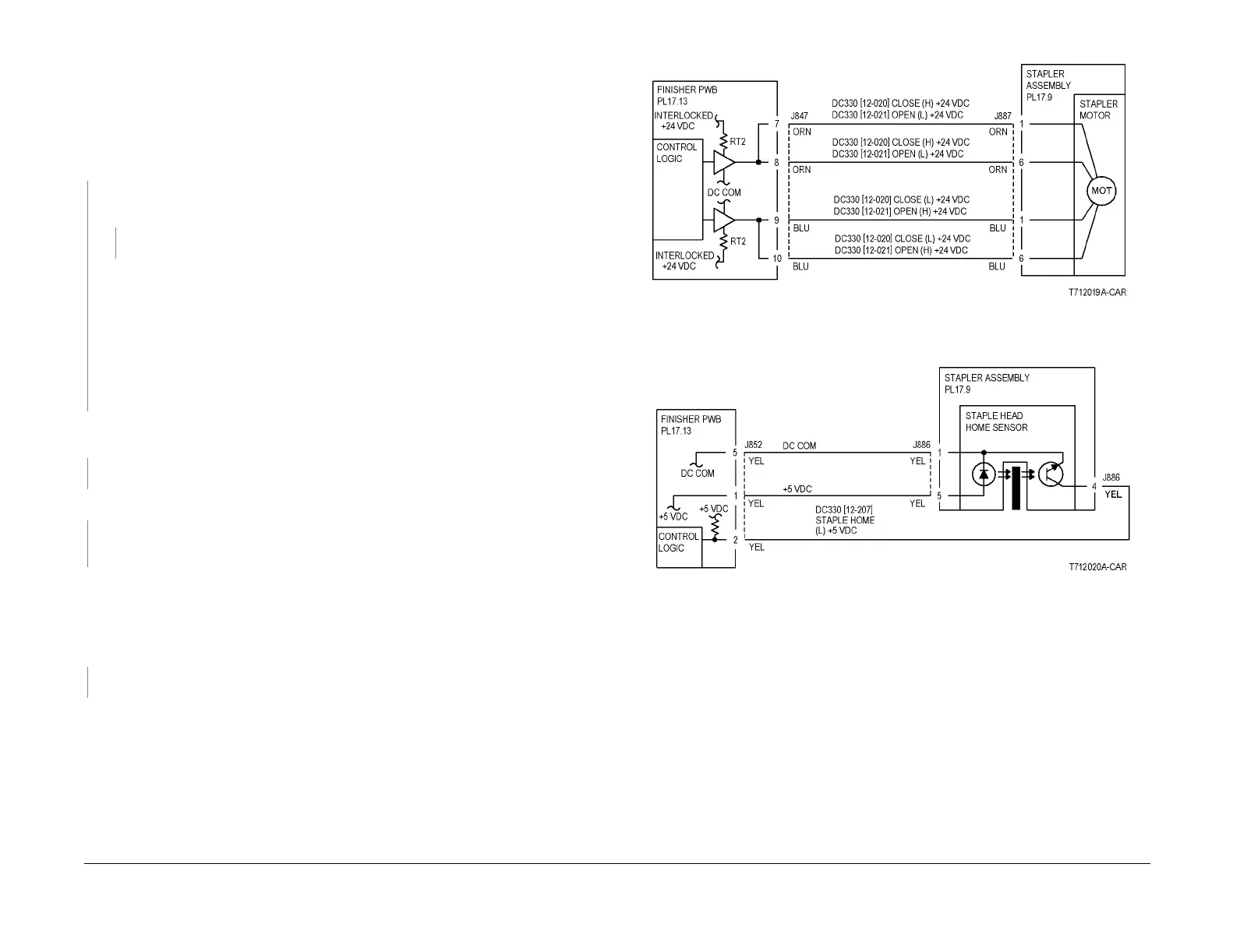
With [12-020] running, +24 VDC is measured between the Finisher PWB P/J847-7
and ground (Figure 1).
YN
Replace the Finisher PWB (PL 17.13) (Figure 3).
Check resistance of the following (Figure 1):
• Between the Finisher PWB P/J847-7 and Stapler Assembly P/J887-1
• Between the Finisher PWB P/J847-8 and Stapler Assembly P/J887-2
• Between the Finisher PWB P/J847 -9 and Stapler Assembly P/J887-3
• Between the Finisher PWB P/J847-10 and Stapler Assembly P/J887-4
If no problems are found, replace the Stapler Assembly (PL 17.9).
If the problem continues, replace the Finisher PWB (PL 17.13).
Turn the gear of the Staple Motor manually to drive the Actuator to block the Staple Head
Home Sensor. +5 VDC is measured between the Finisher PWB P/J852-2 and ground.
YN
Replace the Finisher PWB (PL 17.13).
+5 VDC is measured between the Staple Head P/J886-4 and ground.
YN
Check the wire between the Staple Head P/J886-4 and the Finisher PWB P/J852-2 for
an open circuit or poor contact (Figure 2).
Check resistance of the following:
• Between the Finisher PWB P/J852-1 and the Staple Head P/J886-5
• Between the Finisher PWB P/J852-5 and the Staple Head P/J886-1
Resistance is 1 Ohm or less for both wires.
YN
Repair wires with more than 1 Ohm for an open circuit or poor contact.
Replace the Stapler Assembly (PL 17.9).
If the problem continues, replace the Finisher PWB (PL 17.13).
Figure 1 12-916 RAP Circuit Diagram - Stapler Motor
Figure 2 12-916 RAP Circuit Diagram - Staple Head Home Sensor

 Loading...


