09/03
4-14
DC 3535/2240/1632, WC M24
REP 1.14
Initial issue
Repairs and Adjustments
REP 1.14 PS-1 ROM, PS-2 ROM
Parts List on PL 13.1
Removal
1. Gather all available settings information. This includes the machine NVM log, the
Machine Settings floppy disk, copies of the Configuration Report, etc. If possible save the
current Machine Settings to the floppy.
WARNING
To avoid personal injury or shock, do not perform repair or adjustment activities with
the power switch on or electrical power applied to the machine.
2. Remove the Connector Cover (PL 10.2).
3. Remove the DIMM Cover (PL 13.1).
CAUTION
PWBs can be damaged by electrostatic discharge. Observe all ESD procedures.
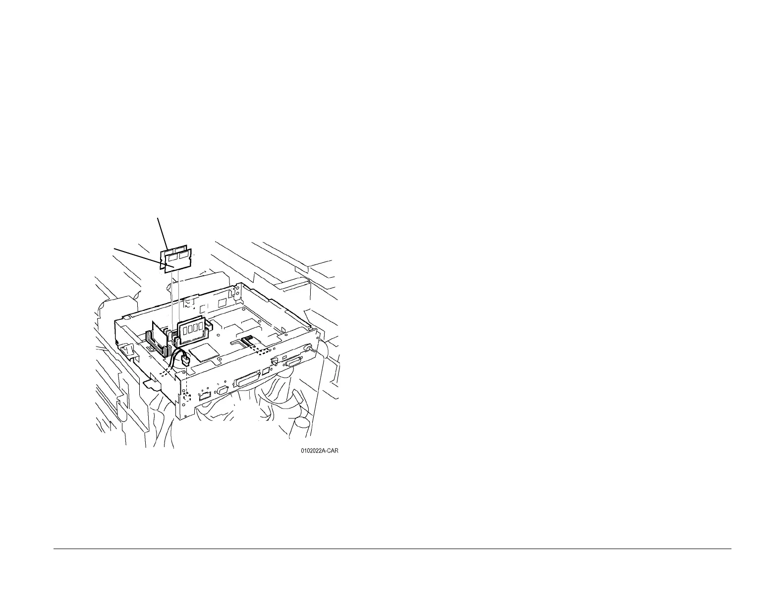
4. Remove the PS-1 ROM (ALL) and/or PS-2 ROM (DC2240/1632) (Figure 1).
Figure 1 Removing PS-1 ROM and PS-2 ROM
Replacement
CAUTION
PS-1 ROM must be installed in R1 slot (front slot) Figure 1.
1. Install the new ROM PWB(s) and reassemble the machine
2. Switch on the power and connect the PWS.
3. If the machine declares a software-related (Chains 102, 103 or 116) fault, there may be
an incompatible version of ESS software in the new ROM PWBs. Reload the correct ESS
software in accordance with the instructions on the s/w upgrade CD.
4. If the machine successfully boots without a fault code, print the Configuration Page.
Check the ESS software version (Standard+PostScript ROM) to ensure that it matches
the system software configuration. Refer to the SW Configuration Table in the system
software upgrade instructions contained on the s/w upgrade CD.
If the software version does not match, reload the software in accordance with the instruc-
tions on the CD.
Remove PS-1 ROM
FRONT
Remove
PS-2
ROM

 Loading...


