09/03
4-5
DC 3535/2240/1632, WC M24
REP 1.4, REP 1.5
Repairs and Adjustments
Initial issue
REP 1.4 3.3 V LVPS or 5 V LVPS
Parts List on PL 9.1
Removal
WARNING
To avoid personal injury or shock, do not perform repair or adjustment activities with
the power switch on or electrical power applied to the ma1chine.
CAUTION
PWBs can be damaged by an electrostatic discharge. Observe all ESD procedures to avoid
component damage.
1. Remove the Rear Cover (REP 14.2).
2. Remove the High Voltage Power Supply Chassis (REP 1.6).
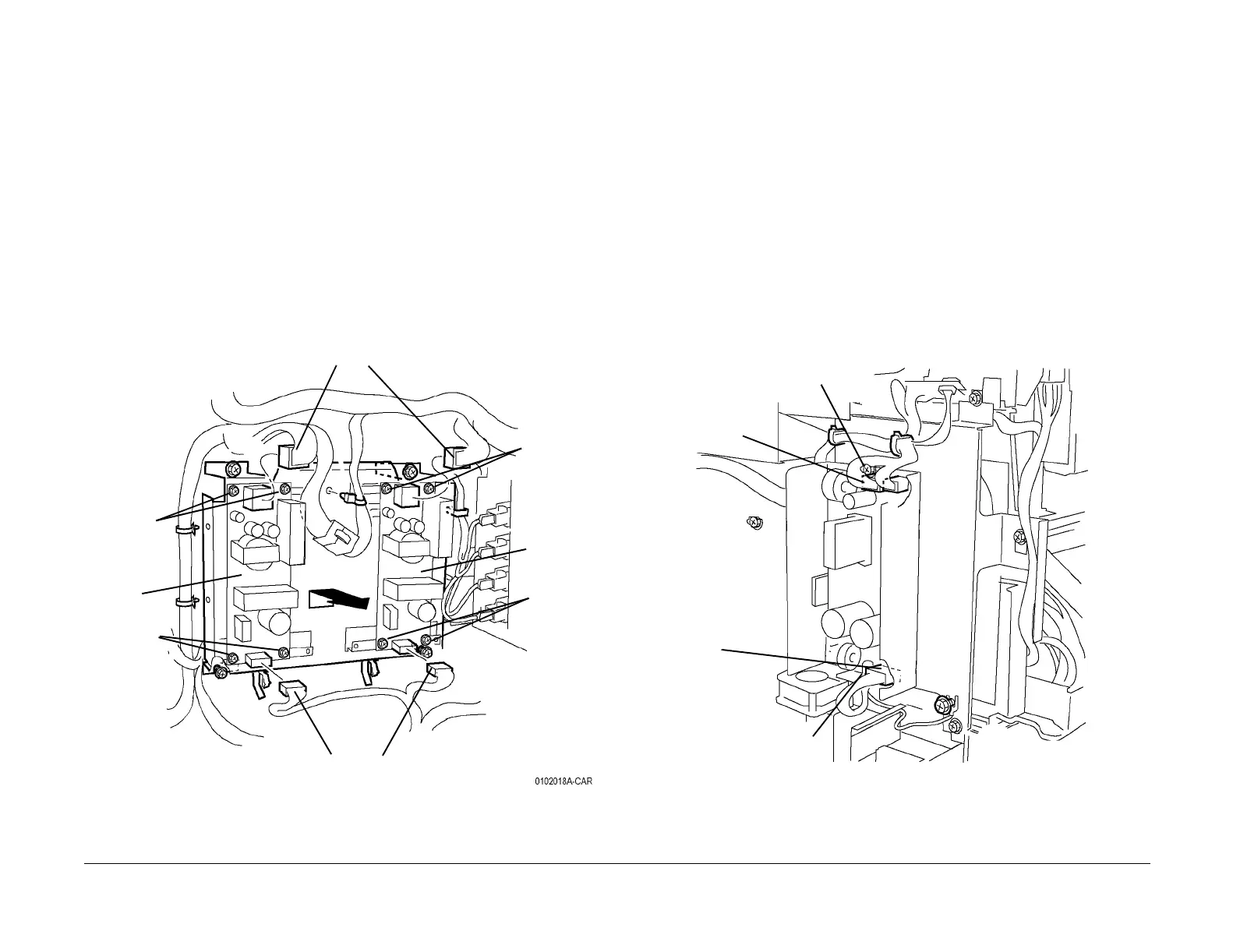
3. Remove the appropriate LVPS (Figure 1).
a. Disconnect appropriate harness connectors (2).
b. Remove the appropriate screws (4) and remove LVPS.
Figure 1 Removing LVPS
REP 1.5 24 V LVPS
Parts List on PL 9.1
Removal
WARNING
To avoid personal injury or shock, do not perform repair or adjustment activities with
the power switch on or electrical power applied to the machine.
1. Remove the Rear Cover (REP 14.2).
CAUTION
PWBs can be damaged by an electrostatic discharge. Observe all ESD procedures to avoid
component damage.
2. Remove the 24 V LVPS (Figure 1).
a. Remove metal cover over power supply (3 screws)
b. Disconnect harness connectors (3).
CAUTION
5 screws with red marks secure LVPS to heat sink. Do not remove them.
c. Loosen screws (2) and remove LVPS.
Figure 1 Removing 24 VDC Power Supply
Screws (2)
Screws
(2)
Screws (2)
Screws
(2)
3.3 VDC
LVPS
5 VDC
LVPS
Harness connectors
Harness connectors
Harness
connector
Screw
Screw
Harness con-
nectors (2)

 Loading...


