09/03
2-109
DC 3535/2240/1632, WC M24
6-381, 6-382
Status Indicator RAPs
Initial issue
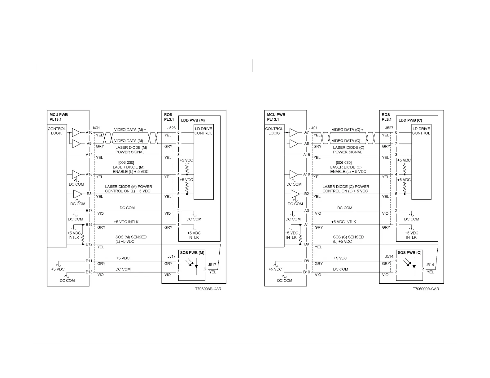
6-381 ROS SOS M Length
The interval of the ROS Start-of-Scan (M) signals exceeds the specified value.
Procedure
+5VDC is measured between the MCU PWB P/J401-B19 (+) and ground (-).
YN
Replace the MCU PWB (PL 13.1).
Refer to Figure 1 and check the wire between the SOS PWB (M) P/J517-2 and the MCU PWB
P/J401-B12 for an open circuit.
Check the wires between P/J528 and the MCU PWB P/J401 for an open circuit.
If no problems are found, replace the ROS Assembly (PL 3.1).
If the problem continues, replace the MCU PWB (PL 13.1).
Figure 1 6-381 RAP Circuit Diagram - ROS SOS M
6-382 ROS SOS C Length
The interval of the ROS Start-of-Scan (C) signals exceeds the specified value.
Procedure
+5VDC is measured between the MCU PWB P/J401-A1 (+) and ground (-).
YN
Replace the MCU PWB (PL 13.1).
Refer to Figure 1 and check the wire between the SOS PWB (C) P/J514-2 and the MCU PWB
P/J401-B9 for an open circuit.
Check the wires between P/J527 and the MCU PWB P/J401 for an open circuit.
If no problems are found, replace the ROS Assembly (PL 3.1).
If the problem continues, replace the MCU PWB (PL 13.1).
Figure 1 6-382 RAP Circuit Diagram - ROS SOS C

 Loading...


