09/03
2-110
DC 3535/2240/1632, WC M24
6-383, 6-385
Initial issue
Status Indicator RAPs
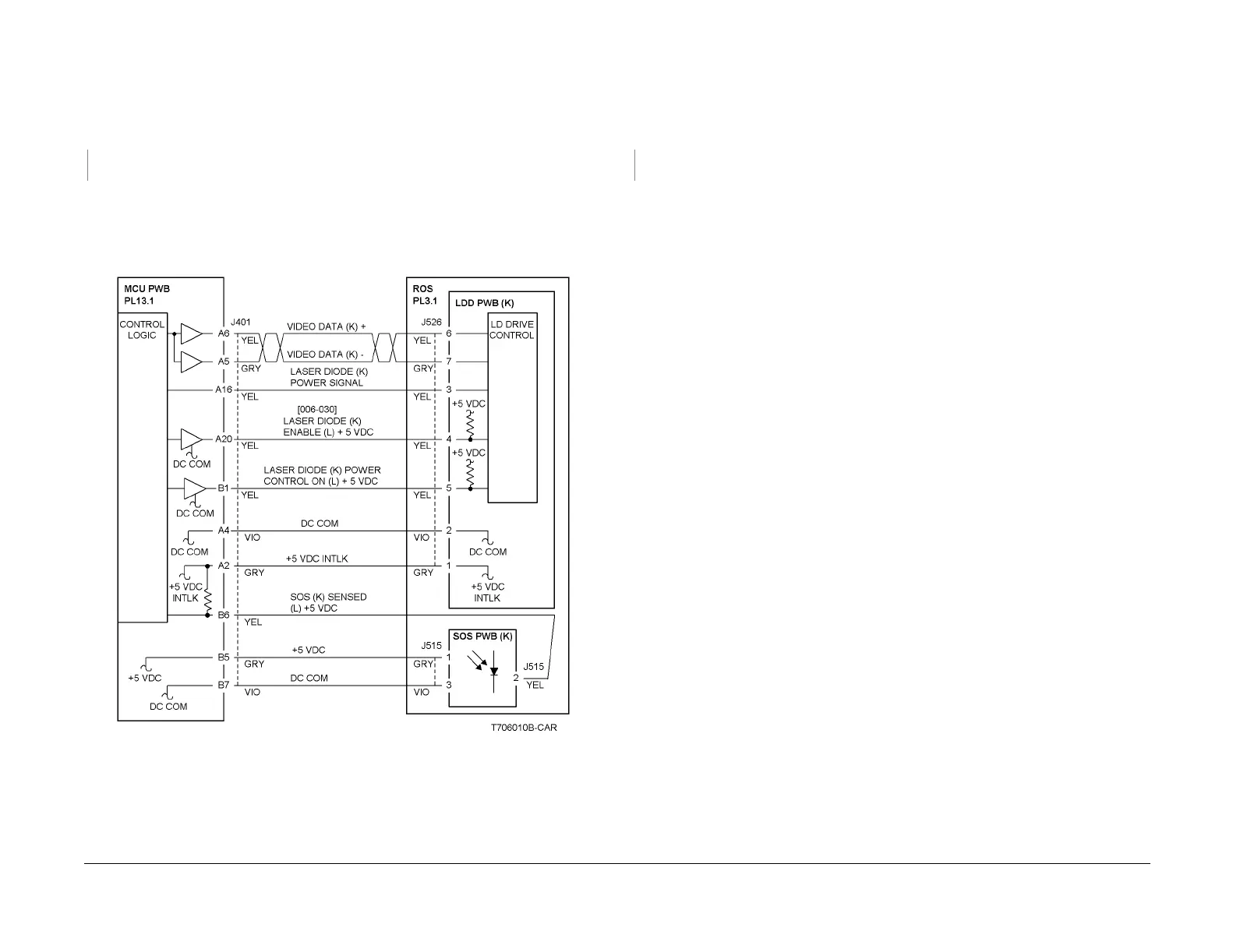
6-383 ROS SOS K Length
The interval of the ROS Start-of-Scan (K) signals exceeds the specified value.
Procedure
+5VDC is measured between the MCU PWB P/J401-A2 (+) and ground (-).
YN
Replace the MCU PWB (PL 13.1).
Refer to Figure 1 and check the wire between the SOS PWB (K) P/J515-2 and the MCU PWB
P/J401-B6 for an open circuit.
Check the wires between P/J526 and the MCU PWB P/J401 for an open circuit.
If no problems are found, replace the ROS Assembly (PL 3.1).
If the problem continues, replace the MCU PWB (PL 13.1).
Figure 1 6-383 RAP Circuit Diagram - ROS SOS K
6-385 ROS ASIC
The Control Logic detected an operation failure of the ROS ASIC in the MCU PWB.
Procedure
Switch power off then on. The problem continues.
YN
Return to Service Call Procedures.
Replace the MCU PWB (PL 13.1).

 Loading...


