09/03
4-172
DC 3535/2240/1632, WC M24
ADJ 9.9
Initial issue
Repairs and Adjustments
ADJ 9.9 IOT Registration Series (dC129)
Purpose
The purpose is to adjust the position of the printed image on the page. This is done by chang-
ing the value in the appropriate NVM location in dC129. This controls where the ROS writes
the image.
Introduction
This series consists of 4 procedures:
Lead Edge Registration (All Trays)
Side Edge Registration (Trays 1-5)
Duplex (Side 2) Registration
Lead Edge Registration for Tray 5
All procedures must be checked.
Lead Edge Registration (All Trays)
Purpose
To correctly set the lead edge of the image in relation to the edge of the paper. There is one
lead edge setting for Trays 1 - 5. The test pattern will print from Tray 1.
Check
1. Connect the PWS to the machine and enter Diagnostic Mode (refer to Entering Diagnostic
Mode using the PWS). Select dC129 from the DC Quick menu.
2. Load Tray 1 with the largest paper used by the customer. Use 11x17/A3 if available.
3. Select ALL in the Lead Edge column.
4. Press the Start button on the screen. As the prints are made, mark each to indicate the
lead edge (flip the sheets from face down to face up without rotating).
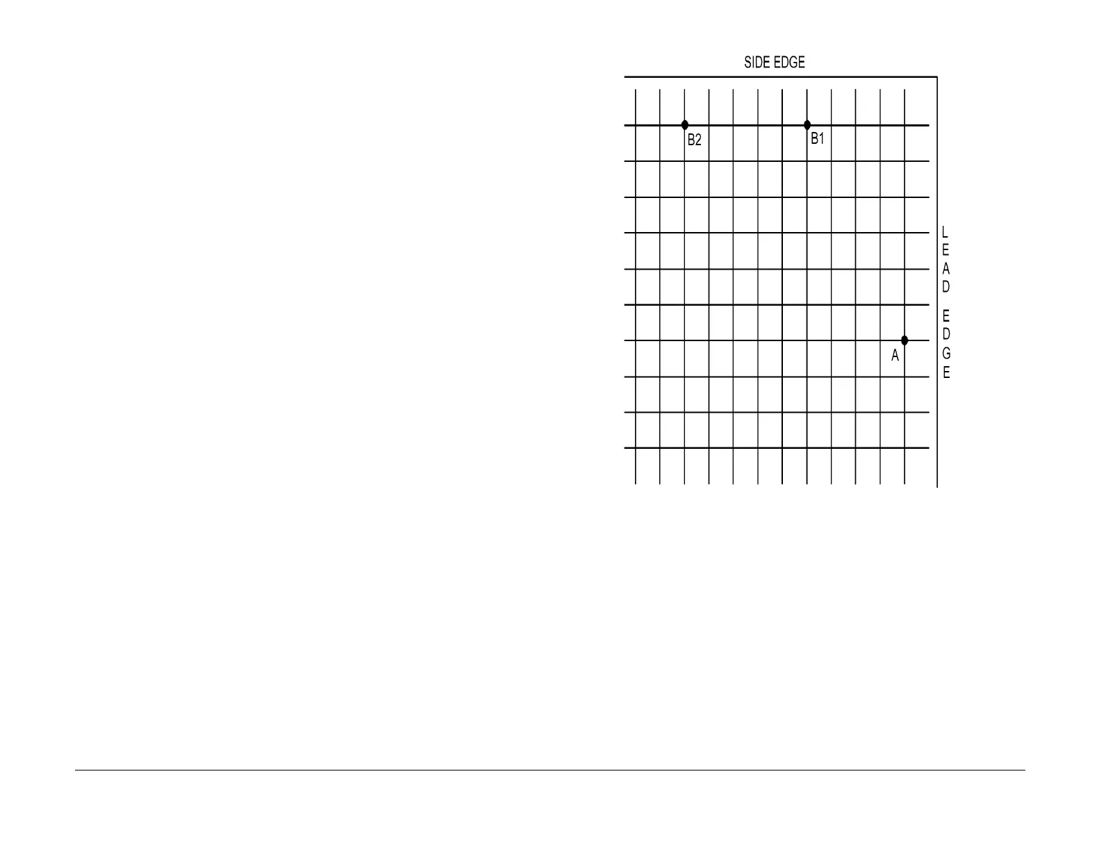
5. Take the third print and measure from the lead edge to point ‘A’ on Figure 1 (the intersec-
tion of the 7th line from the left edge and the first line from the lead edge).
6. If the measured value is not 21.6mm±0.5, perform the Adjustment.
Figure 1 Measurement points
Adjustment
1. Use the Right and Left Arrow buttons to increase or decrease the amount of lead edge
spacing. Use the right arrow to increase the spacing (moves the grid pattern to the left).
Each click moves the image 0.25mm. The cumulative amount of shift is indicated in the
Lead Reg. box.
2. After adjusting the registration, click Set Adjust Value.
NOTE: Changes made to the NVM for LE registration are not implemented unless the machine
exits Diagnostic Mode.
3. Go to the Service Exit tab and select Temporary Closeout.
4. After the machine reboots and is ready to copy, reconnect the PWS.
5. Repeat the check/adjustment until the specifications are met.
6. Select Save [LR] to save the new NVM settings.
7. Proceed to Side Edge Registration for Paper Trays 1 - 5.

 Loading...


