09/03
2-108
DC 3535/2240/1632, WC M24
6-372, 6-380
Initial issue
Status Indicator RAPs
6-372 ROS Polygon Motor
The Control Logic has detected a ROS Motor failure.
Procedure
Enter dC330 [006-031] and select Start. +3.3VDC is measured between the MCU PWB P/
J402 (+) and ground (-)
YN
Go to Flag 1. Check the wire for an open circuit.
+24VDC is measured between P/J402-6 (+) and ground (-).
YN
Replace the MCU PWB (PL 13.1).
Enter dC330 [006-031]. Less than +1.0 VDC is measured between P/J402-4 (+) and
ground (-)
YN
Replace the MCU PWB (PL 13.1).
Approximately +2.5 VAC is measured between P/J402-2 (+) and ground (-).
YN
Replace the MCU PWB (PL 13.1).
Go to Flag 1, Flag 2, Flag 3, and Flag 4. Check the wires for an open circuit or a short circuit to
GND. If no problems are found, replace the ROS (PL 3.1).
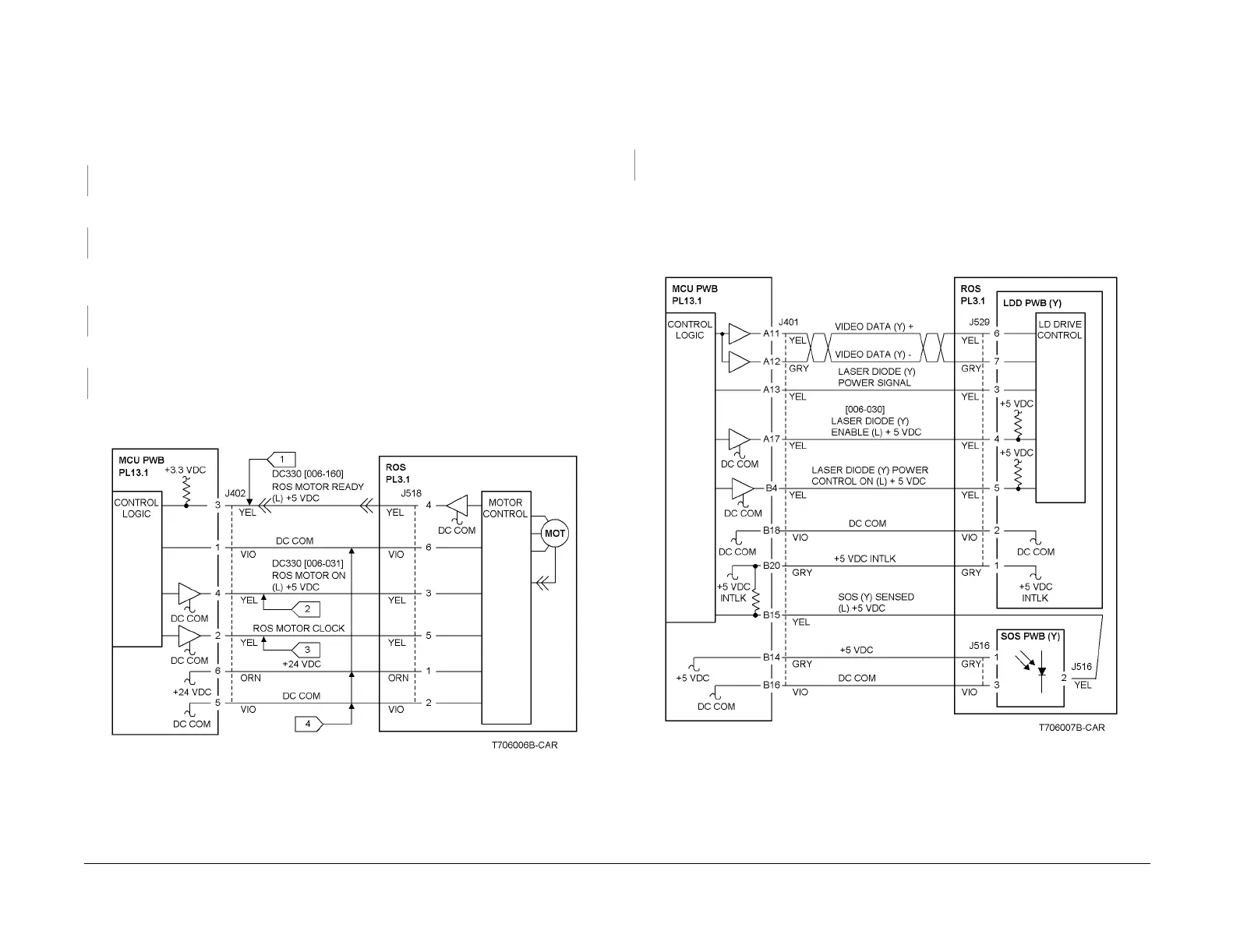
Figure 1 6-372 RAP Circuit Diagram - Polygon Motor Control
6-380 ROS SOS Y Length
The interval of the ROS Start-of-Scan (Y) signals exceeds the specified value.
Procedure
+5VDC is measured between the MCU PWB P/J401-B20 (+) and ground (-)
YN
Replace the MCU PWB (PL 13.1).
Refer to Figure 1 and check the wire between the SOS PWB (Y) P/J516-2 and the MCU PWB
P/J401-B15 for an open circuit.
Check the wires between P/J529 and the MCU PWB P/J401 for an open circuit.
If no problems are found, replace the ROS Assembly (PL 3.1).
If the problem continues, replace the MCU PWB (PL 13.1).
Figure 1 6-380 RAP Circuit Diagram - ROS SOS Y

 Loading...


