09/03
4-43
DC 3535/2240/1632, WC M24
REP 6.3, REP 6.4
Repairs and Adjustments
Initial issue
REP 6.3 IIT Top Cover
Removal
WARNING
To avoid personal injury or shock, do not perform repair or adjustment activities with
the power switch on or electrical power applied to the machine.
1. Remove DADF (REP 5.1).
2. Remove Screws (2) from the top front of IIT Top Cover.
3. Loosen Screws (2) under Control Panel (one each end towards the machine rear).
4. Remove the Screw from the rear of the IIT Top Cover, left side.
5. Remove the Document Output Tray.
6. Remove the Document Output Tray support bracket Screws (4) and Brackets (2).
7. Lift the IIT Top Cover to access harness connectors (2). Disconnect P/J’s and remove IIT
Top Cover.
REP 6.4 Lens Kit
Parts List on PL 18.4
Removal
WARNING
To avoid personal injury or shock, do not perform repair or adjustment activities with
the power switch on or electrical power applied to the machine.
1. Remove Platen Glass (REP 6.2).
CAUTION
In the following, do not remove any screws with red markings.
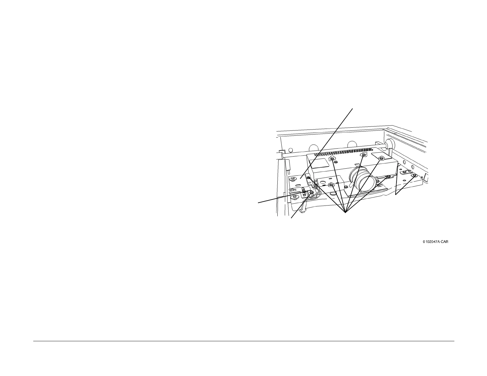
2. Remove the Lens/CCD Chassis (Figure 1).
Figure 1 Removing Lens Cover
Replacement
1. Align APS Sensor with marks made during the removal procedure before tightening the
mounting screw.
2. Adjust the IIT Calibration (ADJ 9.7).
2
Remove the screw (1)
and APS Sensor
bracket
1
Mark the
position of
the APS
Sensor
bracket
3
Remove Lens
Cover screws (6)
and Lens Cover
4
Disconnect CCD Connector
(not shown) and remove
Lens/CCD Chassis screws
(4) (2 each side)
5
Remove the Lens/CCD
Chassis

 Loading...


