09/03
2-93
DC 3535/2240/1632, WC M24
5-700
Status Indicator RAPs
Initial issue
5-700 Set Gate Solenoid RAP
Use this RAP when directed to troubleshoot problems with the DADF Set Gate Solenoid.
Initial Actions
Remove the following:
• Front Cover (PL 20.1)
• Entrance Tray (PL 20.1)
• Lower Chute Assembly (REP 5.8)
• Rear Cover (REP 5.18)
Check the linkage of the Set Gate Solenoid. Check for any binding. Ensure the Set Gate is not
damaged.
Procedure
Switch on the power. +24 VDC is measured between P/J598-2 on the DADF Control PWB
and GND.
YN
Replace the DADF Control PWB (PL 20.3).
+24 VDC is measured between P/J598-3 on the DADF Control PWB and GND.
YN
Check the following
•Go to Flag 2. Check the wire for an open or short circuit.
•Go to Flag 3. Check the wire for an open circuit.
• If the wires are good, replace the Set Gate Solenoid (PL 20.5).
Enter dC330 [005-011]. Select Start. The voltage at P/J598-3 goes to less than +1.0 VDC.
YN
Replace the DADF Control PWB (PL 20.3).
+24 VDC is measured between P/J598-1 on the DADF Control PWB and GND.
YN
Check the following
•Go to Flag 1. Check the wire for an open or short circuit.
• If the wire is good, replace the Set Gate Solenoid (PL 20.5).
Enter dC330 [005-012]. Select Start. The voltage at P/J598-1 goes to less than +1.0 VDC.
YN
Replace the DADF Control PWB (PL 20.3).
The circuit for the DADF Set Gate Solenoid appears to be functioning properly. Look for any
loose or damaged wires. Ensure the solenoid bracket is adjusted so that the plunger for the
solenoid is not binding. If the problem continues, replace the Set Gate Solenoid (PL 20.5). If
the problem continues, replace the DADF Controller PWB (PL 20.3).
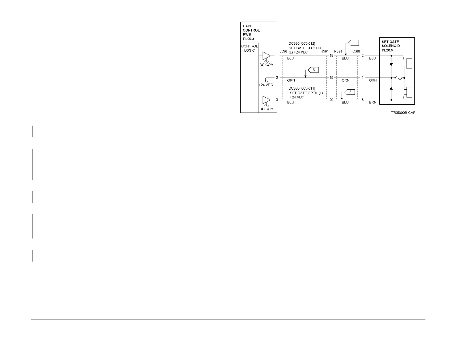
Figure 1 5-700 RAP Circuit Diagram - Set Gate Solenoid

 Loading...


