09/03
4-89
DC 3535/2240/1632, WC M24
REP 9.20, REP 9.21
Repairs and Adjustments
Initial issue
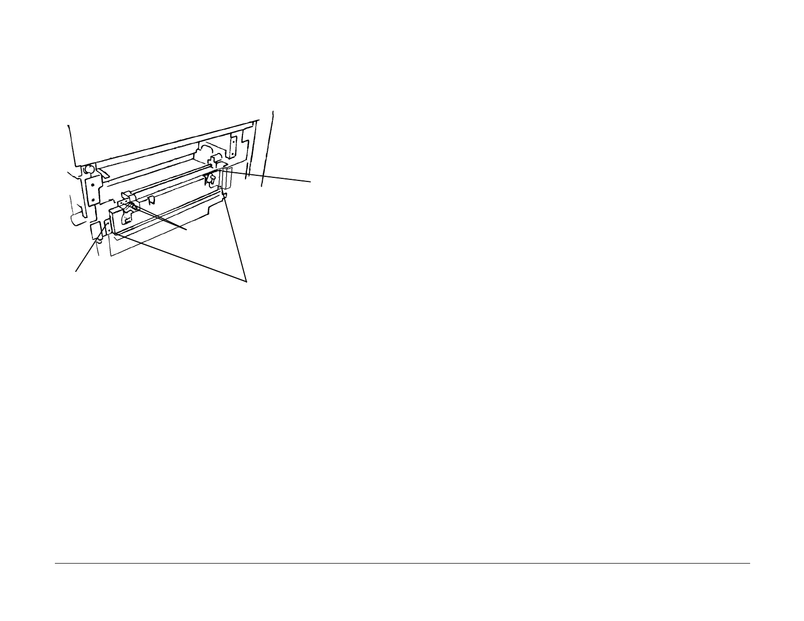
11. Remove Right Lift Assembly (Figure 2).
a. Remove Auger mounting screws (2).
b. Remove lift position screw.
c. Remove secondary position screw.
d. Remove lower screws (2).
e. Remove Right Lift Assembly.
Figure 2 Removing Right Lift Assembly
Replacement
Move Lever to down position before reinstalling IBT Belt Assembly.
REP 9.21 Left Lift Assembly
Parts List on PL 5.1
Removal
WARNING
To avoid personal injury or shock, do not perform repair or adjustment activities with
the power switch on or electrical power applied to the machine.
1. Remove Front Cover (REP 14.7).
2. Remove Lever (REP 9.18).
3. Remove Rear Cover (REP 14.2).
4. Remove Left Lower Cover Assembly (REP 14.6).
5. Remove Tray 5 (REP 7.1).
6. Remove Left Cover Assembly (REP 8.1).
7. Optional for improved visibility: Remove Fuser (REP 10.1).
8. Remove Registration Transport Assembly (REP 8.6).
9. Remove MOB Sensor (REP 9.14).
10. Remove the Duct (PL 8.1, item 7).
11. Remove Left Hinge (REP 9.19).
12. Remove Cyan and Black Toner Cartridges.
13. Remove Cyan and Black Toner Dispensers (REP 9.7).
NOTE: In next step, do not remove the Full Toner Sensor from the sensor housing
In next step, it may not be necessary to disconnect harnesses for Plate Assembly (PL 4.2) to
remove a developer housing.
14. Remove Plate Assembly (REP 9.8).
15. Remove Cyan and Black Developer Housings (REP 9.9).
16. Remove Left Lift Assembly (Figure 1).
NOTE: In next step, use a magnet to capture E-Ring and Washer while removing them.
a. From inside Developer Housing cavity, remove e-ring and washer from each end of
Left Lift.
b. Remove screws (4).
c. Remove Left Lift Assembly.
NOTE: Maintain orientation to ensure bearings (2) and washers (2) do not fall off
posts.
Lift Position
Screw
Lift Secondary
Position Screw
Auger
Mounting
Screws (2)
Lower Screws (2)

 Loading...


