09/03
4-7
DC 3535/2240/1632, WC M24
REP 1.8
Repairs and Adjustments
Initial issue
REP 1.8 I/F (Interface) PWB
Parts List on PL 9.1
Removal
WARNING
To avoid personal injury or shock, do not perform repair or adjustment activities with
the power switch on or electrical power applied to the machine.
1. Remove the Right Cover (REP 14.3).
2. Remove the Top Cover (REP 14.1).
3. Remove the Rear Cover (REP 14.2).
4. Pivot down HVPS Chassis (REP 1.6).
5. Remove ESS DIMM cover (PL 13.1, item 4).
6. Disconnect J300 (DC2240/1632) or NJ300 (DC3535) from the ESS PWB
CAUTION
Disengage locking tab on P/J400 before disconnecting.
CAUTION
PWBs can be damaged by electrostatic discharge. Observe all ESD procedures.
7. Remove the ESS Chassis Assembly (Figure 1).
Figure 1 Removing ESS Chassis
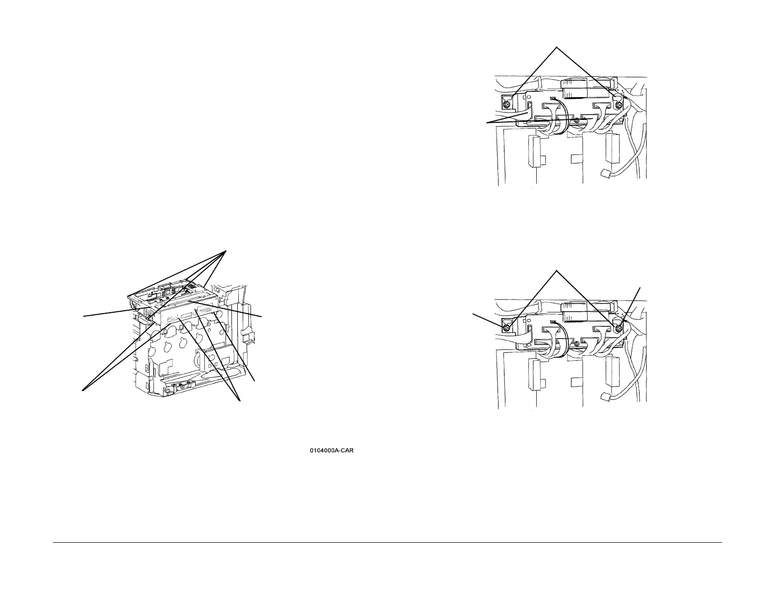
8. Remove the Interface PWB (Figure 2).
a. Loosen screws (2).
b. Lift the Interface PWB until harness connectors (11) can be disconnected.
c. Remove the Interface PWB from chassis
Figure 2 Removing Interface PWB
Replacement
Ensure screws (2) are positioned in slots as shown before tightening (Figure 3).
Figure 3 Installing Interface PWB
4
Remove screws (4)
1
Unlatch Harness Clips
(2)
3
Disconnect
Switch from
chassis
2
Disconnect connectors (8) from MCU PWB
(under chassis)
5
Lift outer end of chas-
sis to disconnect P/
J410 and remove
chassis
P/J400 (see CAUTION)
Screws (2)
Harness
connec-
tors (11)
Screws (2)
Slot
Slot

 Loading...


