09/03
4-85
DC 3535/2240/1632, WC M24
REP 9.14, REP 9.15
Repairs and Adjustments
Initial issue
REP 9.14 MOB Sensor Assembly
Parts List on PL 1.3
Removal
WARNING
To avoid personal injury or shock, do not perform repair or adjustment activities with
the power switch on or electrical power applied to the machine.
1. Open Front Cover.
2. Remove Waste Toner Cartridge (REP 9.4).
3. Remove Fuser Cover (REP 14.8).
4. Remove Dispenser Cover (REP 9.6).
5. Remove Agitator Motor Assembly (REP 9.13).
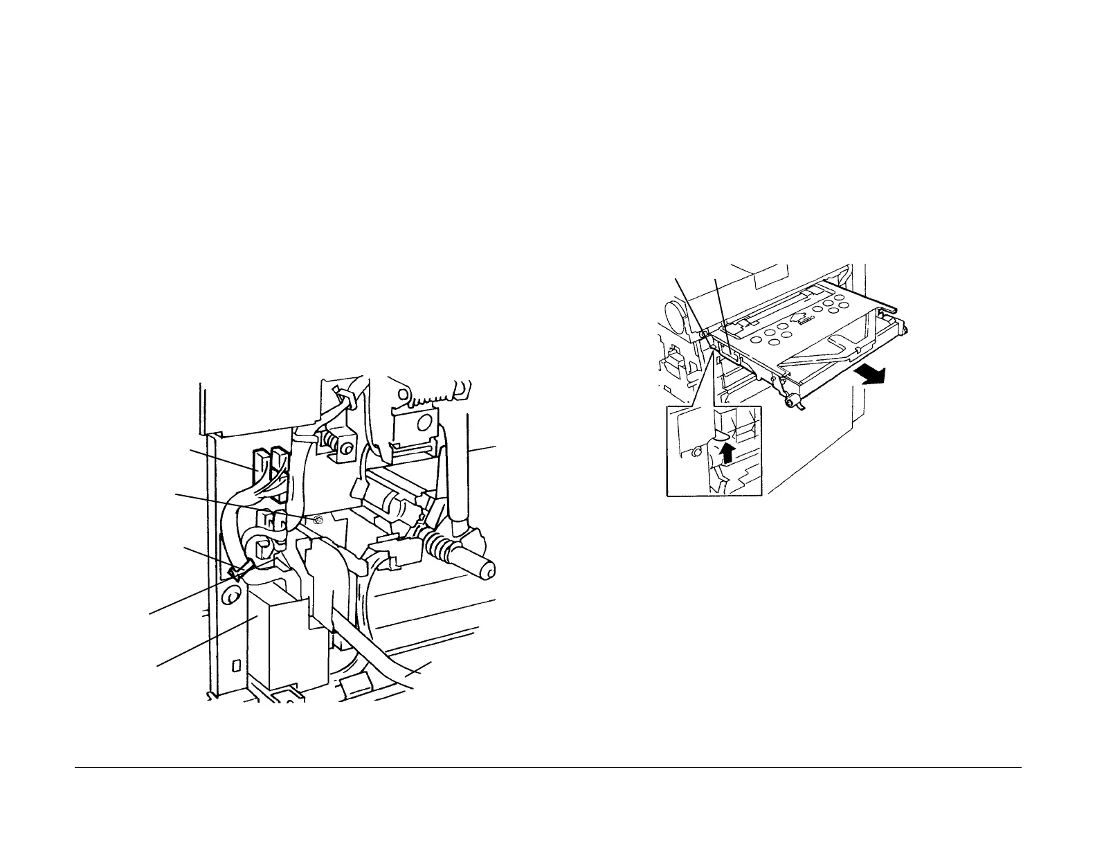
6. Remove MOB Sensor Assembly (Figure 1).
a. Open harness clip and remove harness from clip.
b. Remove screw and remove Inner Cover.
c. Disconnect connectors (3)
d. Remove MOB Sensor Assembly Harnesses (violet) from additional harness clips
(not shown).
e. Remove MOB Sensor Screw and pull out to remove MOB Sensor Assembly. Xero-
graphic Release Lever must be down as shown.
Figure 1 Removing MOB Sensor Assembly
REP 9.15 IBT Belt Assembly
Parts List on PL 5.2
Removal
WARNING
To avoid personal injury or shock, do not perform repair or adjustment activities with
the power switch on or electrical power applied to the machine.
1. Open Front Cover.
2. Release and move Xerographic Release Lever down.
3. Open Right Side Door.
4. Remove IBT Belt Assembly (Figure 1).
a. Lift to release Slide Lock.
b. Pull out IBT Belt Assembly to remove it. Use handle to transport.
Figure 1 Removing IBT Belt Assembly
Replacement
Go to Detailed Maintenance Activities and reset the HFSI counter for IBT Belt Assembly.
Harness Clip
Inner
Cover
Connectors (3)
MOB Sensor
Screw
Xerographic
Release
Lever
Screw
Slide
Lock
Handle

 Loading...


