09/03
4-15
DC 3535/2240/1632, WC M24
REP 1.15
Repairs and Adjustments
Initial issue
REP 1.15 MCU NVM PWB
Parts List on PL 13.1
Removal
1. Gather all available settings information. This includes the machine NVM log, the
Machine Settings floppy disk, copies of the Configuration Report, etc. If possible save the
current Machine Settings to the floppy.
CAUTION
PWBs can be damaged by electrostatic discharge. Observe all ESD procedures.
2. Remove Right Cover (REP 14.3).
3. Remove Top Cover (REP 14.1).
4. Remove Rear Cover (REP 14.2).
5. Remove ESS DIMM cover (PL 13.1, item 4).
6. Disconnect J300 (DC2240/1632) or NJ300 (DC3535) from the ESS PWB
CAUTION
Disengage locking tab on P/J400 before disconnecting.
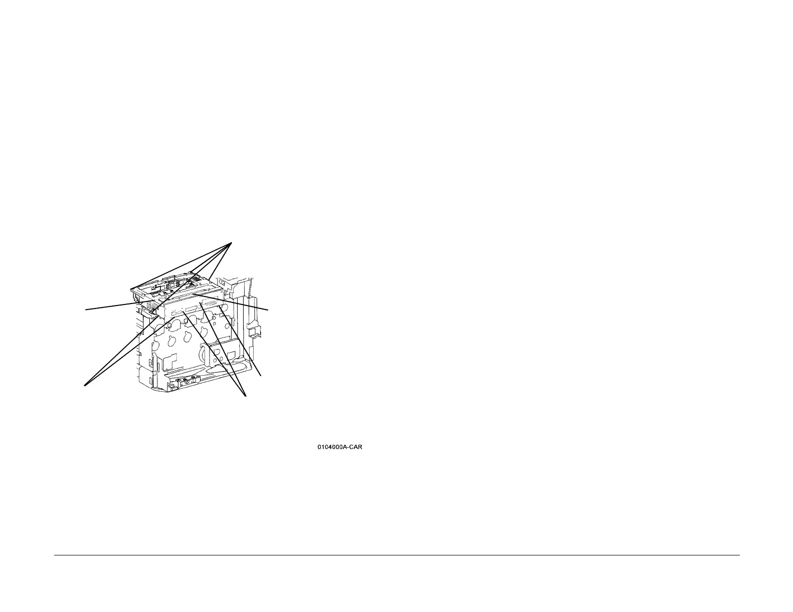
7. Remove the ESS Chassis Assembly (Figure 1).
Figure 1 Removing ESS Chassis
CAUTION
The MCU NVM PWB has a lithium battery. Dispose of the used battery following the manufac-
turers' instructions after replacing. Do not throw it away at customer's site.
8. Remove the screws (9) securing the MCU PWB Cover (PL 13.1) and remove the cover.
9. Remove the MCU NVM PWB (PL 13.1).
Replacement
1. Install the new MCU NVM PWB and reassemble the machine. Connect the PWS and
switch on the power.
CAUTION
GP10 is used to maintain the integrity of the serial number and billing data, when one or more
serialized PWBs must be replaced.
To maintain the integrity of the serial number and billing data, never replace all three listed
PWBs at the same time. If any of the following billing data PWBs needs replacing, only replace
them one at a time.
• ESS NVM PWB (PL 13.1).
• MCU PWB (PL 13.1).
• ESS PWB (PL 13.1).
Failure to comply with the board replacement procedure in GP 10 could result in catastrophic
NVM corruption.
2. Follow the procedure in GP 10. If two or more serial numbers DO NOT match the M/C
label serial number, escalate the service call to Field Engineering or the NTC.
3. If a good Machine Settings floppy is available, exit, then reenter the PWS Tool. Select
Read from Floppy when starting the tool. If no floppy is available, or if the data on the
existing floppy is questionable, go to step 5.
4. Go to dC351 and select Restore Machine Settings. When restoration is complete, go to
step 7.
5. If a good Machine Settings floppy is not available, or if the data on the existing floppy is
questionable, go to dC351. In the Special Batch Write area, select the appropriate market
region, then press the Batch Write NVM button.
6. Using the resources gathered in step 1 of the removal procedure, reenter NVM data to
restore the machine configuration.
7. Ensure that the network information (IP address, etc.) is correct. Contact the customer’s
system administrator to configure, if necessary.
4
Remove screws (4)
1
Unlatch Harness Clips
(2)
3
Disconnect
Switch from
chassis
2
Disconnect connectors (8) from MCU PWB
(under chassis)
5
Lift outer end of chas-
sis to disconnect P/
J410 and remove
chassis
P/J400 (see CAUTION)

 Loading...


