09/03
2-186
DC 3535/2240/1632, WC M24
9-351
Initial issue
Status Indicator RAPs
9-351 Drive Logic
The IBT Edge Sensor detected that the IBT Belt is not tracking correctly.
Initial Actions
• Check the IBT Edge Sensor for damage. Ensure that the actuator is touching the edge of
the belt.
• Check the IBT steering drives for damage.
Procedure
Switch on the power. There is +1VDC to +3VDC from P/J533-A11 to GND.
YN
There is +5VDC measured between P/J533-A10 and P/J533-A9 on the I/F PWB.
YN
Replace the MCU PWB (PL 13.1).
There is +5VDC from P/J 533-A11 on the I/F PWB to GND.
YN
Go to Figure 2. Check the connectors and wires. If the check is OK, replace the IBT
Edge Sensor (PL 5.4). If the problem continues, replace the MCU PWB (PL 13.1).
Replace the IBT Sensor (PL 5.4).
Remove the IBT Assembly. Enter dC330 [004-001]. The IBT Steering Motor rotates.
YN
There is +24 VDC from P/J550 on the I/F PWB to GND.
YN
Go to the +24 VDC Wirenets (Figure 2) and troubleshoot the problem.
Check the wires (Figure 1) from P/J550 on the I/F PWB to P/J207 on the IBT Steering
Motor for shorts, opens, or loose connections. If the wires are OK, replace the MCU PWB
(PL 13.1). if the problem persists replace the I/F PWB (PL 9.1), then the IBT Steering
Motor (PL 1.3).
Check the installation of the Transfer Belt and the IBT Assembly (PL 5.3). Repair or replace as
required. If the check is good, replace the MCU PWB (PL 13.1).
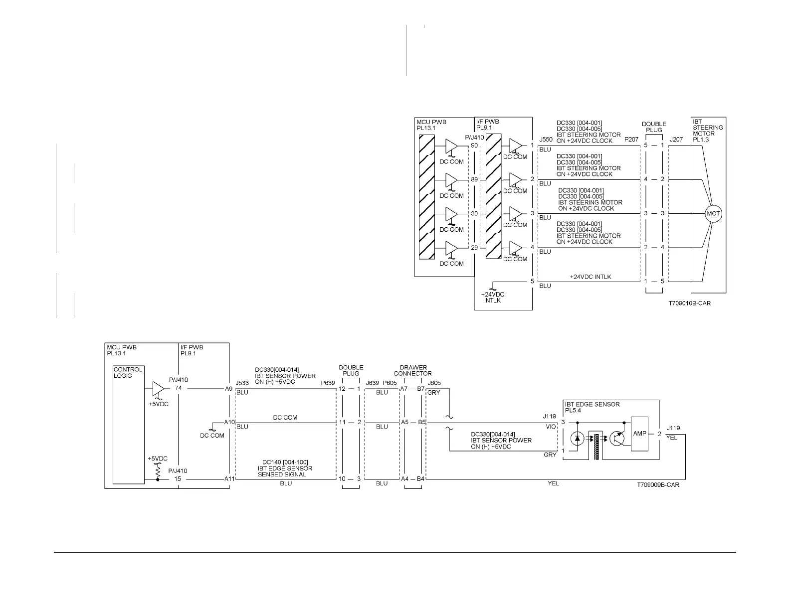
Figure 1 9-351 Rap Circuit Diagram - IBT Steering Motor
Figure 2 9-351 Rap Circuit Diagram - IBT Edge Sensor
A
A
B
B

 Loading...


