09/03
4-19
DC 3535/2240/1632, WC M24
REP 4.1
Repairs and Adjustments
Initial issue
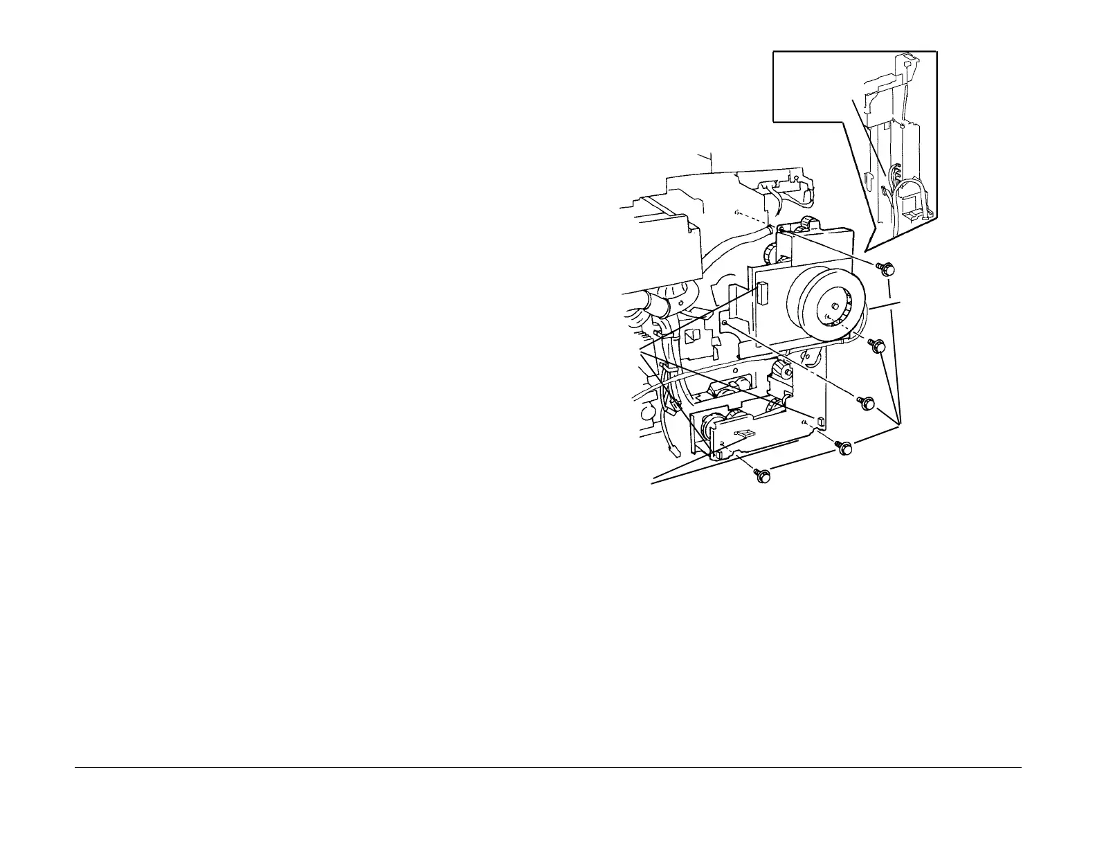
REP 4.1 Main Drive Motor Assembly
Parts List on PL 1.1
Removal
WARNING
To avoid personal injury or shock, do not perform repair or adjustment activities with
the power switch on or electrical power applied to the machine.
1. Remove Fuser Module (REP 10.1).
2. Remove Tray 5 (REP 7.1).
3. Remove Rear Cover (REP 14.2).
4. Remove 24 VDC LVPS Chassis (REP 1.9).
5. Remove BTR1 High Voltage Power Supply (REP 1.10).
6. Remove AC Drive PWB (REP 1.11).
NOTE: Carefully observe position of wiring harnesses for later reinstallation
NOTE: In next step, do not remove small round head screws that appear to secure Main Drive
Motor Assembly to machine.
7. Remove Main Drive Motor Assembly (Figure 1).
Figure 1 Removing Main Drive Motor Assembly
3
Release Harness
Clips (3) (2 not
shown)
2
Disconnect
Connectors
(3)
5
Disconnect HV Wire
1
Disconnect
Connectors (5)
4
Remove Hex Head
screws (DO NOT
remove 5 round
head screws)

 Loading...


