09/03
2-104
DC 3535/2240/1632, WC M24
6-355
Initial issue
Status Indicator RAPs
6-355 IPS Fan
The control logic detects an IPS Fan failure.
Procedure
Enter dC330 [006-014] and select Start. The IPS FAN (PL 18.4) energizes.
YN
Switch off the power. Remove the Platen Glass (REP 6.2) and the IPS Cover (PL 18.3).
Switch on the power. Enter dC330 [006-014] and select Start. +24VDC is measured
between the IIT/IPS PWB P/J722-B8 (+) and GND.
YN
Replace the IIT/IPS PWB (PL 18.3).
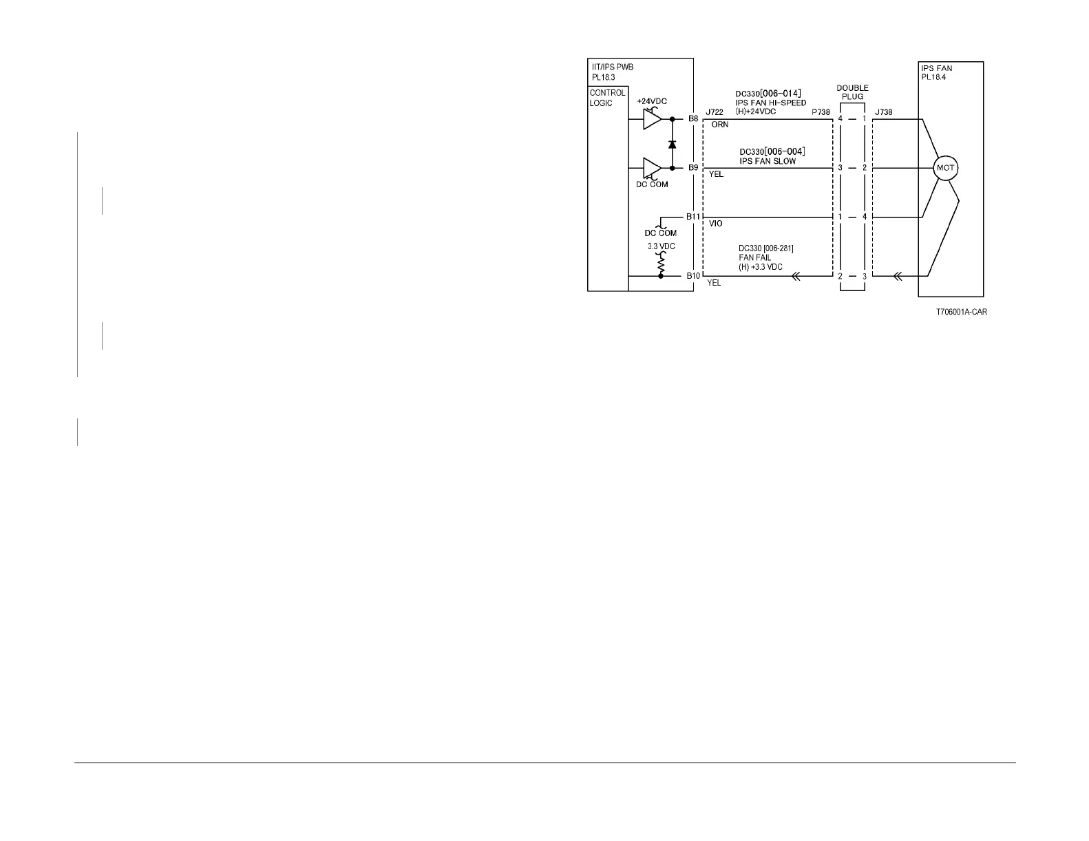
Switch the power off. Check the continuity of the following (Figure 1).
• Between the IIT/IPS PWB P/J722-B8 and the IPS FAN P/J738-1
• Between the IIT/IPS PWB P/J722-B9 and the IPS FAN P/J738-2
• Between the IIT/IPS PWB P/J722-B10 and the IPS FAN P/J738-3
• Between the IIT/IPS PWB P/J722-B11 and the IPS FAN P/J738-4
Less than 5 ohms is measured.
YN
Repair the wire.
Replace the IPS FAN (PL 18.4).
Switch off the power. Remove the Platen Glass (REP 6.2) and the IPS Cover (PL 18.3). Switch
on the power. +3.3 VDC is measured at the IIT/IPS P/J722-B10
YN
Replace the IIT/IPS PWB (PL 18.3).
Check the wire from IIT/IPS PWB P/J722-B10 to the IPS Fan connector P/J738-3 for an open
circuit. If the wire is good, replace the IPS FAN (PL 18.4).
Figure 1 6-355 RAP Circuit Diagram - IPS Fan

 Loading...


