09/03
2-87
DC 3535/2240/1632, WC M24
5-116
Status Indicator RAPs
Initial issue
5-116 Exit Sensor Off
The document does not deactuate the DADF Exit Sensor after the DADF Exit Sensor actuated.
Initial Actions
Check the customer’s documents to ensure they meet the specification for the DADF.
Ensure the Exit Roll and Exit Pinch Roll are clean and properly installed (PL 20.9).
Procedure
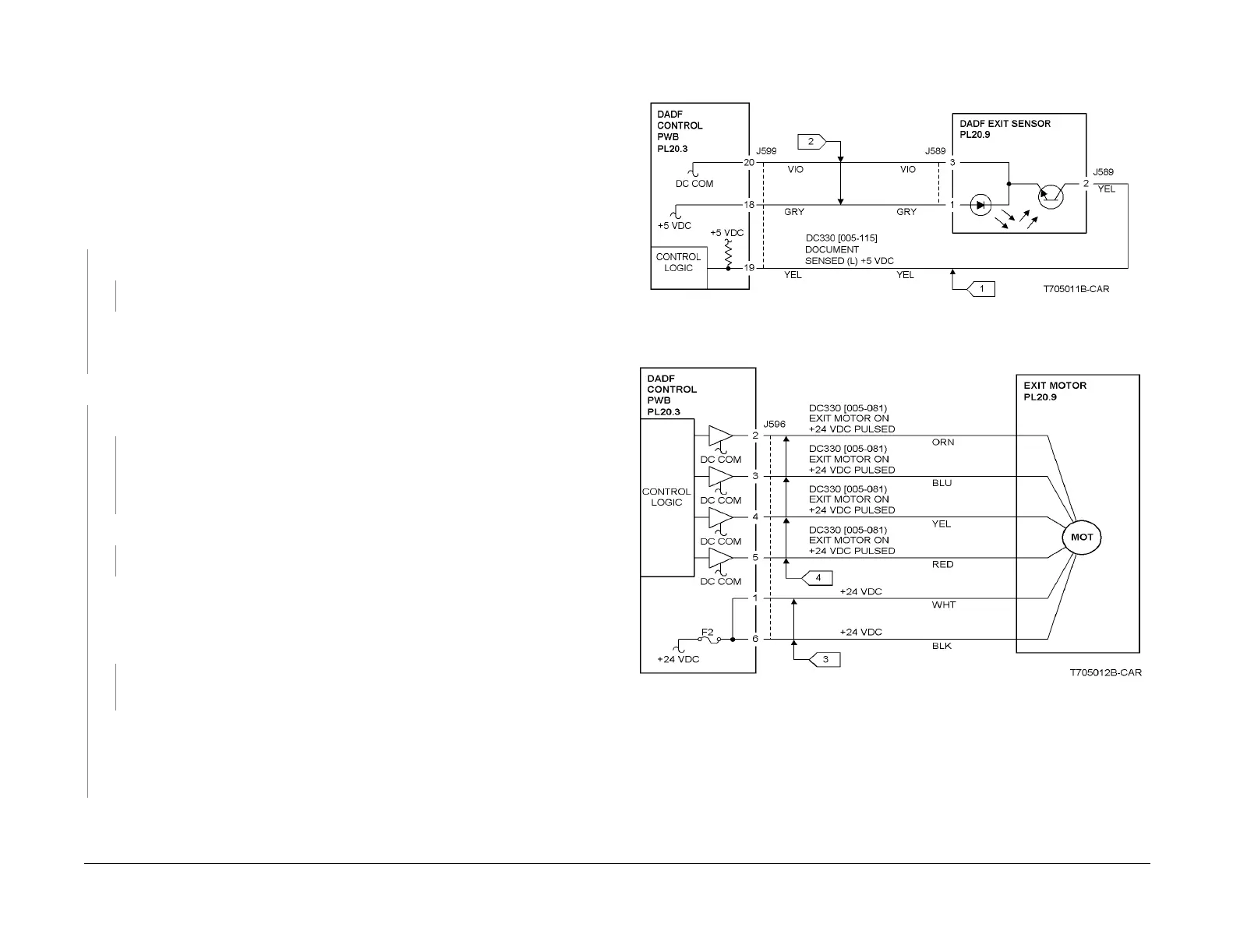
Enter dC330 [005-115] and press Start. Actuate the DADF Exit Sensor (PL 20.9). The dis-
play changes.
YN
The display indicates H.
YN
Go to Flag 1. Check the wire for a short circuit to GND.
Go to Flag 1 and Flag 2. Check the wires for an open circuit. If the wires are good, replace
the DADF Exit Sensor (PL 20.9). If the problem continues, replace the DADF Control
PWB (PL 20.3).
Enter dC330 [005-081] and press Start. DADF Exit Motor operates.
YN
Check Fuse F2 on the DADF Control PWB. The Fuse is good.
YN
If a fuse is not available, replace the DADF Control PWB (PL 20.3).
Check the +24 VDC wires on the DADF Exit Motor for a short circuit to frame.
If the wires are good, and the problem continues, replace the DADF Exit Motor (PL
20.9).
+24 VDC is measured between P/J596-1 on the DADF Control PWB and GND.
YN
Replace the DADF Control PWB (PL 20.3).
NOTE: In the following step, one of the pins to the motor ( P/J596-2, 3, 4, or 5) will mea-
sure approximately +2 to +5 VDC. This is normal operation.
+24 VDC is measured between P/J596-2, 3, 4, or 5 on the DADF Control PWB and
GND.
YN
Go to Flag 3 and Flag 4. Check the wires for an open circuit. If the wires are good,
replace the DADF Exit Motor (PL 20.9).
Check the following:
• Look for binding in the exit drives (PL 20.9).
• Replace the DADF Exit Motor (PL 20.9).
• If the problem continues, replace the DADF Control PWB (PL 20.3).
Check the following:
• Exit Roll for contamination, wear and a rotation failure (PL 20.9).
• Exit Upper/lower Chute for deformation (PL 20.9).
• Static Eliminator for deformation (PL 20.9).
• Exit Roll Drive Belt for disengagement and damage (PL 20.9).
Figure 1 5-116 RAP Circuit Diagram - DADF Exit Sensor
Figure 2 5-116 RAP Circuit Diagram - Exit Motor

 Loading...


