09/03
4-58
DC 3535/2240/1632, WC M24
REP 7.5, REP 7.6
Initial issue
Repairs and Adjustments
REP 7.5 Tray 1 Paper Size Sensor
Parts List on PL 2.1
Removal
WARNING
To avoid personal injury or shock, do not perform repair or adjustment activities with
the power switch on or electrical power applied to the machine.
1. Remove Rear Cover (REP 14.2).
2. Remove High Voltage Power Supply Chassis (REP 1.6).
NOTE: Step 3 can be omitted if Low Voltage Power Supply P/J’s are disconnected before per-
forming step 4.
3. Remove 3.3 VDC and 5 VDC Low Voltage Power Supply (REP 1.4).
4. Remove Chassis for 3.3 VDC and 5 VDC Low Voltage Power Supply.
a. Release harnesses from harness clips (3).
b. Remove screws (4) and remove Chassis.
5. Remove Developer Drive Module (REP 4.3).
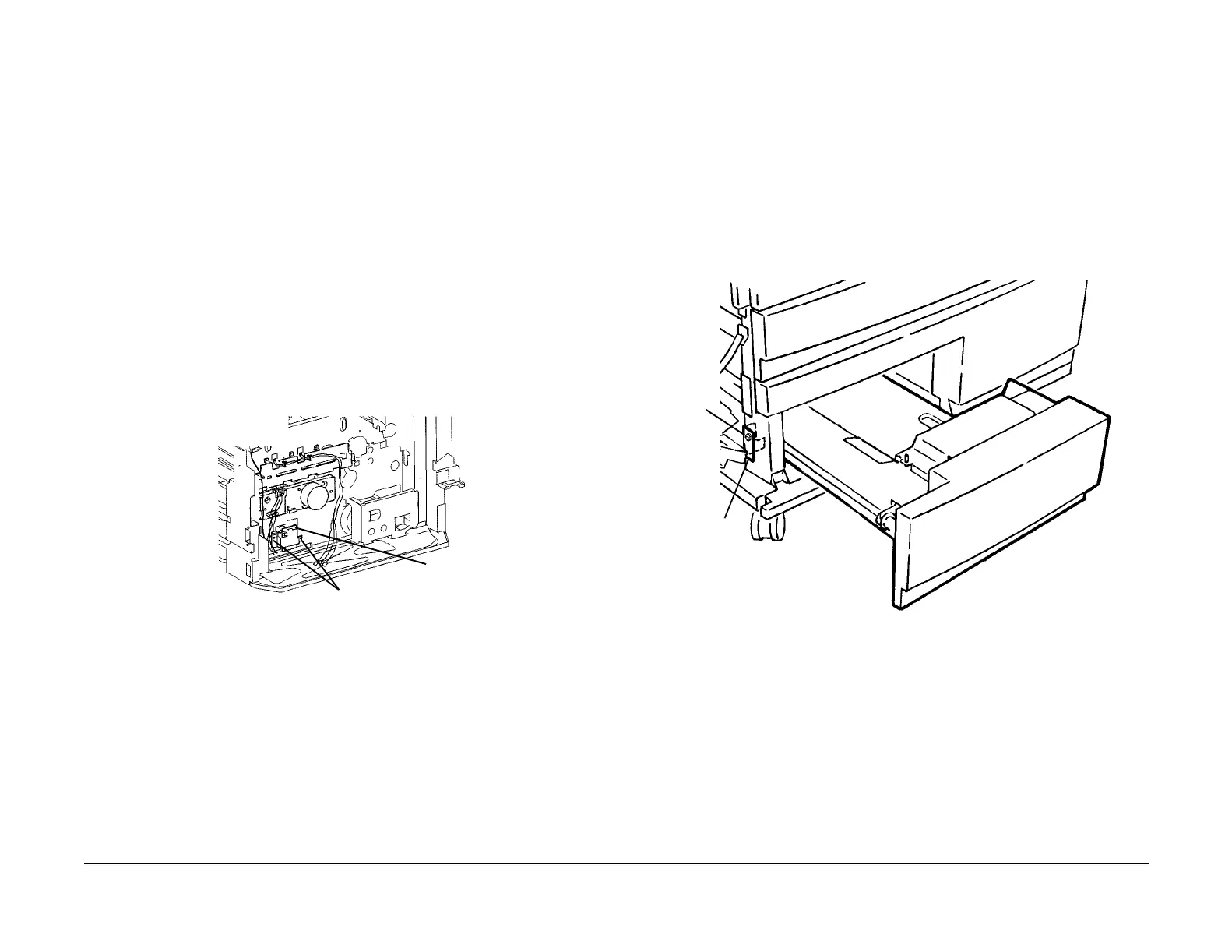
6. Remove Tray 1 Paper Size Switch (Figure 1).
a. Disconnect P/J.
b. Remove Screws (2) and remove Tray 1 Paper Size Switch.
Figure 1 Removing Tray Paper Size Switch
REP 7.6 Tray 3 (TTM)
Parts List on PL 16.1
Removal
WARNING
To avoid personal injury or shock, do not perform repair or adjustment activities with
the power switch on or electrical power applied to the machine.
1. Open the Left Cover Assembly.
2. Remove Tray 3 (Figure 1).
a. Pull out Tray 3.
b. Remove Screw.
c. Pivot bottom of Tray Lock away from Tray 3 and pull out Tray 3 to remove it.
Figure 1 Removing Tray 3
P/J
Screws (2)
Screw
Bottom of
Tray Lock

 Loading...


