09/03
2-649
DC 3535/2240/1632, WC M24
116-324, 116-325
Status Indicator RAPs
Initial issue
116-324 Exception Error
CPU exceptional error.
Initial Actions
Switch power off then on. If the problem persists, continue with the procedure.
Procedure
Perform GP 3. If the problem continues, reload system software. If the problem persists,
replace the ESS PWB (PL 13.1).
116-325 ESS Fan
ESS Fan failure is detected or +24 VDC is failed.
Procedure
• Remove Rear Cover (REP 14.2).
• Remove cover from +24V LVPS (PL 9.1).
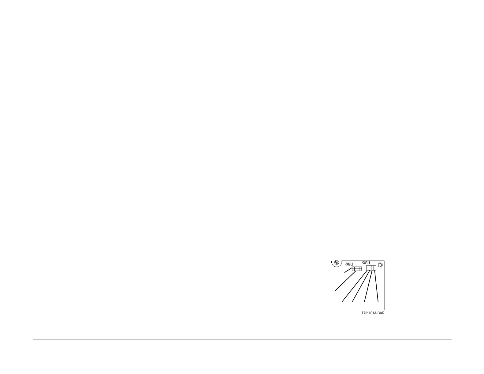
• Disconnect P502 on +24V LVPS (Figure 1).
Check that power is switched off. Measure resistance of fuse on +24V LVPS. Resistance is 1
ohm or less.
YN
Replace +24V LVPS (PL 9.1).
Switch on the power. Measure the AC voltage between the white and black wires in P/J2 on
the +24 VDC. Line Voltage AC is measured.
YN
Go to the OF 1-4 RAP.
Connect the black meter lead to ground (-). Measure DC voltage at P/J505 on the +24V LVPS
(Figure 1). Voltages are measured as shown (Figure 1).
YN
There is a problem with the +24 VDC enable circuit. Go to OF 1-3.
Ensure P/J502 is still disconnected on the +24V LVPS. Measure the DC voltage at P/J502 on
the +24V LVPS (Figure 1). Voltages are measured as shown.
YN
Replace the 24V LVPS (PL 9.1).
Connect P/J502 on the +24V LVPS. Measure the DC voltage at P/J502 on the +24V LVPS
(Figure 1). Voltages are measured as shown.
YN
There is a short circuit in +24 VDC distribution. Refer to Section 7 wirenets for +24 VDC
distribution. Disconnect the connectors in the distribution network. Switch the power on.
Connect the connectors while monitoring +24 VDC. The +24 VDC supply will shut down
when the P/J with the shorted circuit is connected.
Replace the ESS Fan (PL 13.1).
If the problem continues, replace the ESS PWB (PL 13.1).
Figure 1 P502, P505 on +24V LVPS
+24V, 0V, +3.3V, +5V
+24 VDC RET
Vio (all on top)
+24 VDC
Orn (all)

 Loading...


