09/03
4-8
DC 3535/2240/1632, WC M24
REP 1.9, REP 1.10
Initial issue
Repairs and Adjustments
REP 1.9 24 V LVPS Chassis
Parts List on PL 9.1
Removal
WARNING
To avoid personal injury or shock, do not perform repair or adjustment activities with
the power switch on or electrical power applied to the machine.
1. Remove the Rear Cover (REP 14.2).
2. Remove the Rear Left Middle Cover (REP 14.4).
3. Remove the 24 V LVPS (REP 1.5).
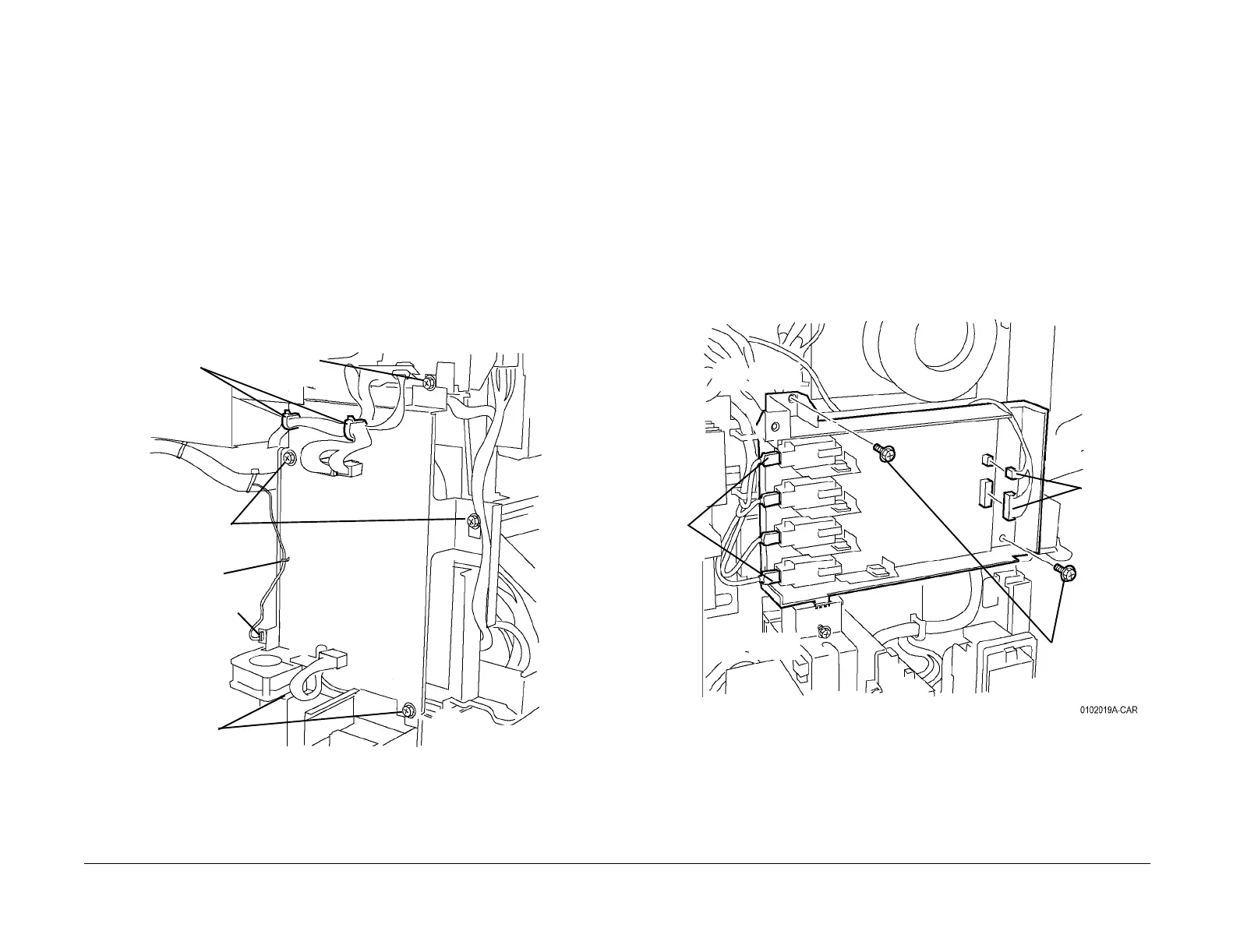
4. Remove the 24 VDC LVPS Chassis (Figure 1).
a. Remove the Top screw.
b. Remove upper harnesses from Harness Clips (2).
c. Disconnect Fan connector and remove harness from Harness Clip.
d. Loosen Screws (4).
e. Remove the 24 VDC LVPS Chassis.
Figure 1 Removing 24 VDC LVPS Chassis Assembly
REP 1.10 BTR1 HVPS
Parts List on PL 9.1
Removal
WARNING
To avoid personal injury or shock, do not perform repair or adjustment activities with
the power switch on or electrical power applied to the machine.
1. Remove the Rear Cover (REP 14.2).
2. Remove the 24 VDC LVPS Chassis (REP 1.9).
3. Remove the BTR1 HVPS (Figure 1).
a. Disconnect connectors (4).
b. Disconnect harness connectors (2).
c. Remove the Screws (2) and remove High Voltage Power Supply with chassis.
d. Remove the High Voltage Power Supply from chassis.
Figure 1 Removing BTR1 HVPS
Harness
Clips
Harness Clip
Fan connector
Screws (2)
Screws (2)
Top
Screw
1st BTR
connec-
tors (4)
Harness
connec-
tors (2)
Screws
(2)
K
C
M
Y

 Loading...


