09/03
4-6
DC 3535/2240/1632, WC M24
REP 1.6, REP 1.7
Initial issue
Repairs and Adjustments
REP 1.6 High Voltage Power Supply Chassis
Parts List on PL 9.1
Removal
WARNING
To avoid personal injury or shock, do not perform repair or adjustment activities with
the power switch on or electrical power applied to the machine.
CAUTION
HVPS can be damaged by an electrostatic discharge. Observe all ESD procedures to avoid
component damage.
1. Remove the Rear Cover (REP 14.2).
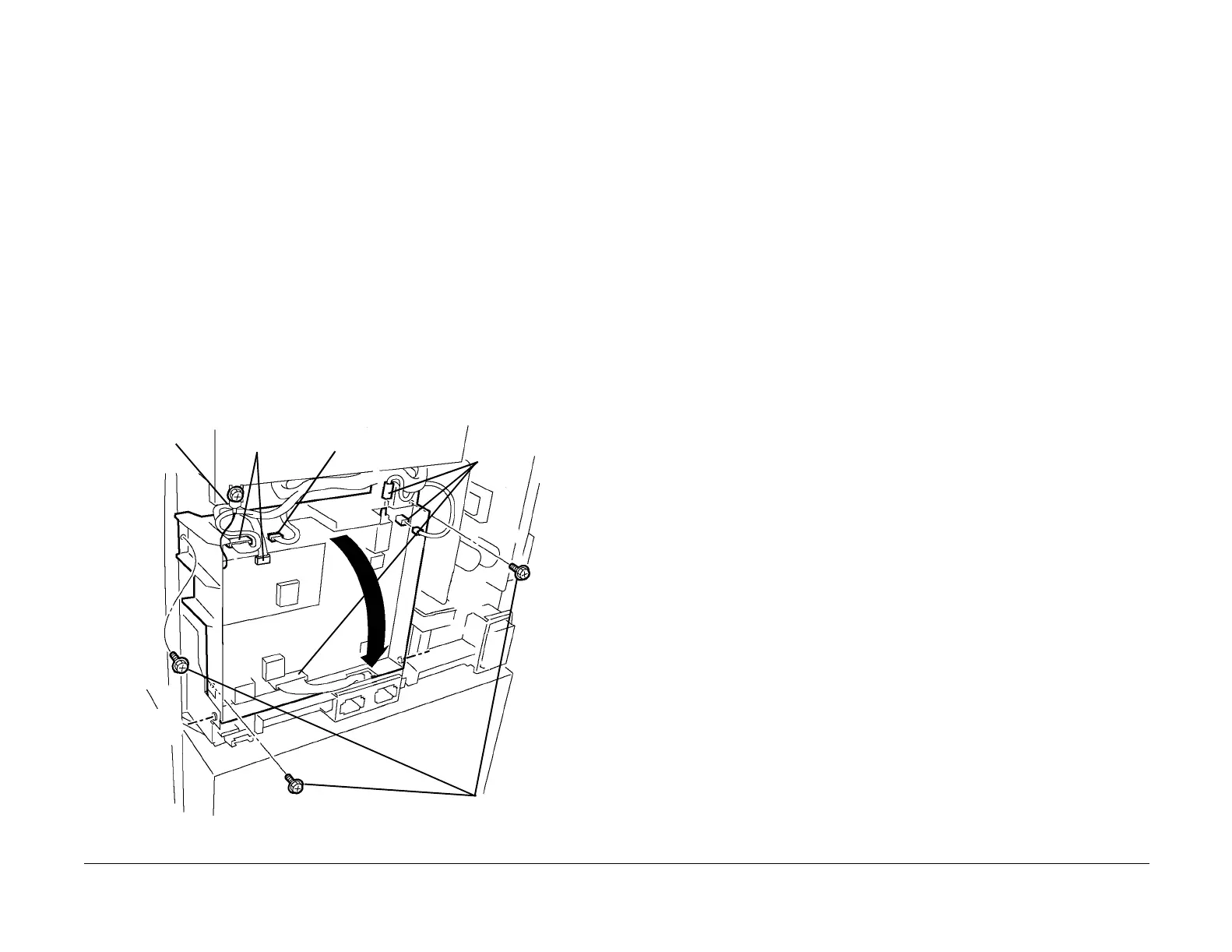
2. Remove the High Voltage Power Supply Chassis (Figure 1).
a. Loosen screw and disconnect ground wire.
CAUTION
Do not attempt to disconnect soldered connection.
b. Disconnect harness connectors (2).
c. Disconnect High Voltage connectors (3).
d. Remove the screws (3).
e. Pivot HVPS down and engage stop strap with frame tab (not shown).
f. Disconnect High Voltage connector (1) from inner PWB (not shown).
Figure 1 Removing High Voltage Power Supply Chassis
REP 1.7 DEV/BTR2/DTS HVPS; BCR HVPS
Parts List on PL 9.1
Removal
WARNING
To avoid personal injury or shock, do not perform repair or adjustment activities with
the power switch on or electrical power applied to the machine.
1. Remove the Rear Cover (REP 14.2).
CAUTION
PWBs can be damaged by an electrostatic discharge. Observe all ESD procedures to avoid
component damage.
2. Remove the High Voltage Power Supply Chassis (REP 1.6).
3. Remove the High Voltage Power Supplies from Chassis:
• DEV/BTR2/DTS HVPS is PWB toward machine rear.
• BCR HVPS is PWB toward machine front.
Soldered
connection
Harness con-
nectors (2)
High Volt-
age con-
nectors
(3)
Screws (3)
Ground
Wire

 Loading...


