09/03
2-194
DC 3535/2240/1632, WC M24
9-410
Initial issue
Status Indicator RAPs
9-410 Toner Cartridge (Y) Near Empty
The Yellow Toner Cartridge is nearly empty/empty. This fault requires service only if the mes-
sage appears before the Toner Cartridge is depleted.
NOTE: Continuous running of high density prints can temporarily deplete the toner supply.
Initial Actions
• Ensure that there is toner and the toner is evenly distributed in the cartridge (Y).
• Check the ATC Sensor (Y) for blockage or contaminants.
• Check the drive system from the Developer Drive Motor to the Developer Housing (Y) for
damage.
Procedure
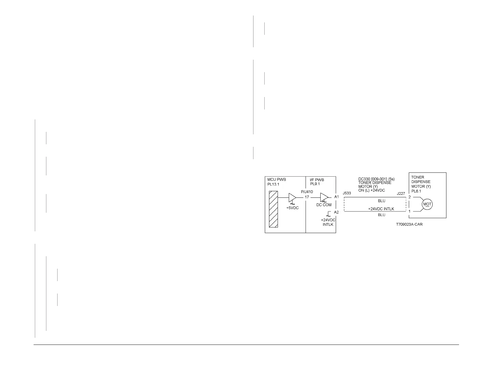
Enter dC330 [009-001] and press Start. The Yellow Toner Dispense Motor (PL 6.1) ener-
gizes.
YN
Go to Figure 1. There is +24 VDC from P/J533-A2 to GND.
YN
Go to the +24 VDC Wirenets (Figure 2) and troubleshoot the problem.
There is +24 VDC from P/J533-A1 to GND.
YN
Check the wires from P/J533 to P/J227 for an open circuit. If the wires are OK,
replace the Yellow Toner Dispense Motor (PL 6.1).
Enter dC330 [009-001]. The voltage from P/J533-A1 to GND drops to less than 1
VDC.
YN
Replace the MCU PWB (PL 13.1). If the problem continues, replace the I/F PWB (PL
9.1).
Check the wires from P/J533 to P/J227for an open circuit. If the wires are OK, replace the
Yellow Toner Dispense Motor (PL 6.1).
The machine is a DC3535.
YN
Enter dC330 [009-014] and press Start. The Developer Motor energizes (PL 1.1).
YN
Go to Figure 2. There is +24VDC from P/J534-A3 to A4 on the I/F PWB (PL 9.1).
YN
Go to the +24 VDC Wirenets (Figure 2) and troubleshoot the problem.
There is +5VDC from P/J534-A8 to A9 on the I/F PWB.
YN
Go to the +5VDC Wirenets (Figure 3) and troubleshoot the problem.
Check the wires between P/J534 on the I/F PWB and P/J232 at the Developer Motor
for opens, shorts, or loose connections. If the wires are OK, replace the Developer
Motor (PL 1.1). If the problem continues, replace the MCU PWB (PL 13.1).
Check ADJ 9.3. The ATC Sensor (Y) fail judgement is OK.
YN
Go to the 9-380 ATC Sensor Failure RAP.
After checking that no failures are detected during normal operation, go to call closeout.
Enter dC330 [009-014] and press Start. The Developer Motor (PL 1.1) energizes.
YN
Go to Figure 3. There is +24VDC from P/J535-A11 to A10 on the I/F PWB (PL 9.1).
YN
Go to the +24 VDC Wirenets (Figure 2) and troubleshoot the problem.
There is +5VDC from P/J535-A1 to A2 on the I/F PWB.
YN
Go to the +5 VDC Wirenets (Figure 3) to troubleshoot the problem.
Check the wires between P/J535 on the I/F PWB and P/J232 on the Developer Motor for
opens, shorts, or loose connections. If the wires are OK, replace the Developer Motor (PL
1.1). If the problem continues, replace the MCU PWB (PL 13.1).
Check ADJ 9.3. The ATC Sensor (Y) fail judgement is OK.
YN
Go to the 9-380 ATC Sensor Failure RAP.
After checking that no failures are detected during normal operation, go to call closeout.
Figure 1 9-410 Rap Circuit Diagram - Toner Dispenser Motor Y
A
A

 Loading...


