09/03
4-4
DC 3535/2240/1632, WC M24
REP 1.2
Initial issue
Repairs and Adjustments
REP 1.2 MCU PWB
Parts List on PL 13.1
Removal
WARNING
To avoid personal injury or shock, do not perform repair or adjustment activities with
the power switch on or electrical power applied to the machine.
1. Gather all available settings information. This includes the machine NVM log, the
Machine Settings floppy disk, copies of the Configuration Report, etc. If possible save the
current Machine Settings to the floppy.
CAUTION
PWBs can be damaged by an electrostatic discharge. Observe all ESD procedures to avoid
component damage.
2. Remove Right Cover (REP 14.3).
3. Remove Top Cover (REP 14.1).
4. Remove Rear Cover (REP 14.2).
5. Remove ESS DIMM cover (PL 13.1, item 4).
6. Disconnect J300 (DC2240/1632) or NJ300 (DC3535) from the ESS PWB.
CAUTION
Disengage locking tab on P/J400 before disconnecting.
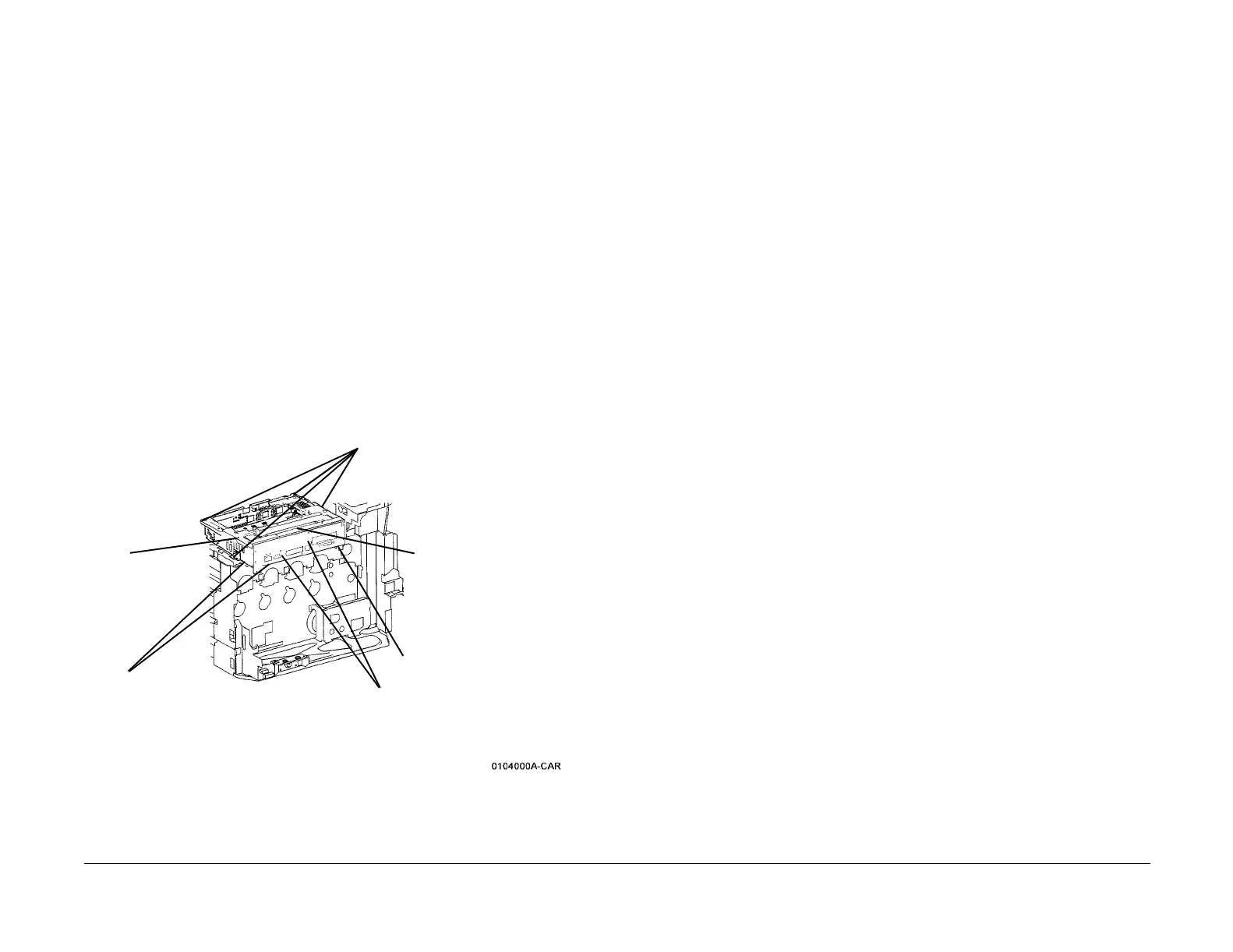
7. Remove the ESS Chassis Assembly (Figure 1).
Figure 1 Removing ESS Chassis
8. Remove the screws (9) securing the MCU PWB Cover (PL 13.1) and remove the cover.
9. Remove and retain the MCU NVM PWB.
10. Remove the screws (5) securing the MCU PWB and remove the MCU PWB.
Replacement
1. Install the existing MCU NVM PWB onto the new MCU PWB. Install the new MCU PWB
and reassemble the machine.
2. Connect the PWS and switch on the power.
3. Check the IOT software version to ensure that it matches the system software configura-
tion. Refer to the SW Configuration Table in the System Software Upgrade Instructions
contained on the S/W Update CD.
If the software version does not match, reload the software in accordance with the instruc-
tions on the CD.
4. If a good Machine Settings floppy is available, exit, then reenter the PWS Tool. Select
Read from Floppy when starting the tool. If no floppy is available, or if the data on the
existing floppy is questionable, go to step 6.
5. Go to dC351 and select Restore Machine Settings. When the restoration is complete,
go to step 8.
6. If a good Machine Settings floppy is not available, or if the data on the existing floppy is
questionable, go to dC351. In the Special Batch Write area, select the appropriate market
region, then press the Batch Write NVM button.
7. Using the resources gathered in step 1 of the removal procedure, reenter NVM data to
restore the machine configuration.
8. Ensure that the network information (IP address, etc.) is correct. Contact the customer’s
system administrator to configure, if necessary.
9. Go to dC351 and select Save Machine Settings. Save the settings to floppy disk per the
procedure.
4
Remove screws (4)
1
Unlatch Harness Clips
(2)
3
Disconnect
Switch from
chassis
2
Disconnect connectors (8) from MCU PWB
(under chassis)
5
Lift outer end of chas-
sis to disconnect P/
J410 and remove
chassis
P/J400 (see CAUTION)

 Loading...


