09/03
2-288
DC 3535/2240/1632, WC M24
12-910
Initial issue
Status Indicator RAPs
12-910 Staple Feed Ready
• At the staple preparation operation at initialization, the Staple Ready Sensor does not go
to ready (L) status after 13 ready attempts.
• The Stapler Ready Sensor is turned off (H) just before the Staple.
Procedure
Remove the Stapler Assembly with a connector connected (REP 12.11). Enter dC330 [012-
209] and press Start. Actuate the Staple Ready Sensor. The display changes.
YN
+5 VDC is measured between the Stapler Assembly P/J886-5 and ground.
YN
+5 VDC is measured between the Finisher PWB P/J852-1 and ground.
YN
Replace the Finisher PWB (PL 17.13) (Figure 3).
Check the wire between the Finisher PWB P/J852-1 and the Stapler Assembly P/
J886-5 for an open circuit or poor contact (Figure 1).
Pull out the staple cartridge. +5 VDC is measured between the Finisher PWB P/J852-
3 and ground.
YN
Switch off the power. Disconnect P/J852 on the Finisher PWB. Switch the power
on. +5 VDC is measured between the Finisher PWB P852-3 and ground.
YN
Replace the Finisher PWB (PL 17.13).
Check the circuit between the Finisher PWB P852 and the Stapler Assembly P/J for
obvious damage (Figure 2).
If the wires are good, replace the Stapler Assembly (PL 17.9).
Replace the Finisher PWB (PL 17.13).
Restore the Staple Head to the original status and cheat the Front Interlock Switch.
Position paper in stapler. Enter dC330 [012-020] and press Start. The Staple Motor ener-
gizes.
YN
With [12-020] running, +24 VDC is measured between the Finisher PWB P/J847-7
and ground.
YN
Replace the Finisher PWB (PL 17.13).
Check resistance of the following (Figure 2):
• Between the Finisher PWB P/J847-7 and Stapler Assembly P/J887-1
• Between the Finisher PWB P/J847-8 and Stapler Assembly P/J887-2
• Between the Finisher PWB P/J847 -9 and Stapler Assembly P/J887-3
• Between the Finisher PWB P/J847-10 and Stapler Assembly P/J887-4
If no problems are found, replace the Stapler Assembly (PL 17.9).
If the problem continues, replace the Finisher PWB (PL 17.13).
Switch the power off. Remove the Stapler Assembly (REP 12.11).
Rotate the Staple Motor Gear manually. The staple needles fed.
YN
Replace the Stapler Assembly (PL 17.9).
Replace the Finisher PWB (PL 17.13).
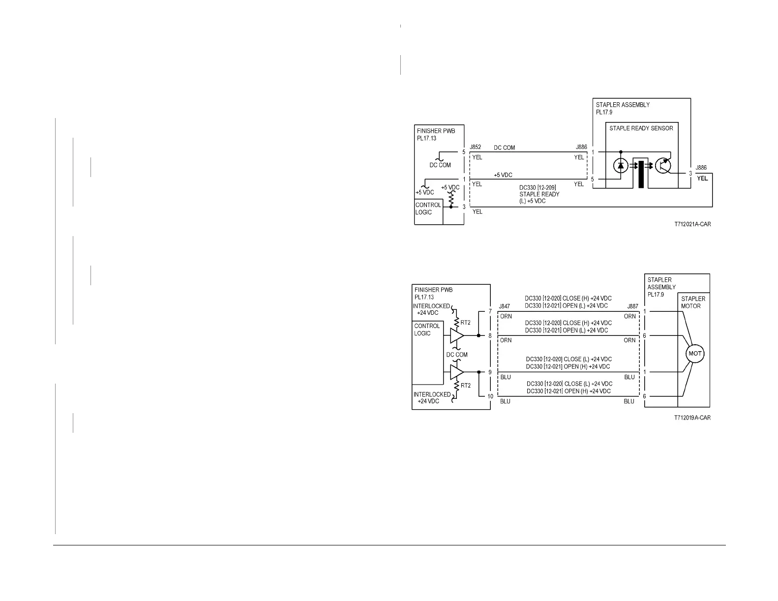
Figure 1 12-910 RAP Circuit Diagram - Staple Ready Sensor
Figure 2 12-910 RAP Circuit Diagram - Staple Motor
A
A

 Loading...


