09/03
4-33
DC 3535/2240/1632, WC M24
REP 5.12, REP 5.13
Repairs and Adjustments
Initial issue
REP 5.12 Size Sensors 1/2 (Rear/Front)
Parts List on PL 20.5
Removal
WARNING
To avoid personal injury or shock, do not perform repair or adjustment activities with
the power switch on or electrical power applied to the machine.
1. Open the DADF Top Cover.
2. Remove the DADF Front Cover (PL 20.1).
3. Remove the Entrance Tray (PL 20.1).
4. Remove Lower Chute Assembly (REP 5.8).
5. Remove Set Gate Solenoid Assembly (REP 5.10).
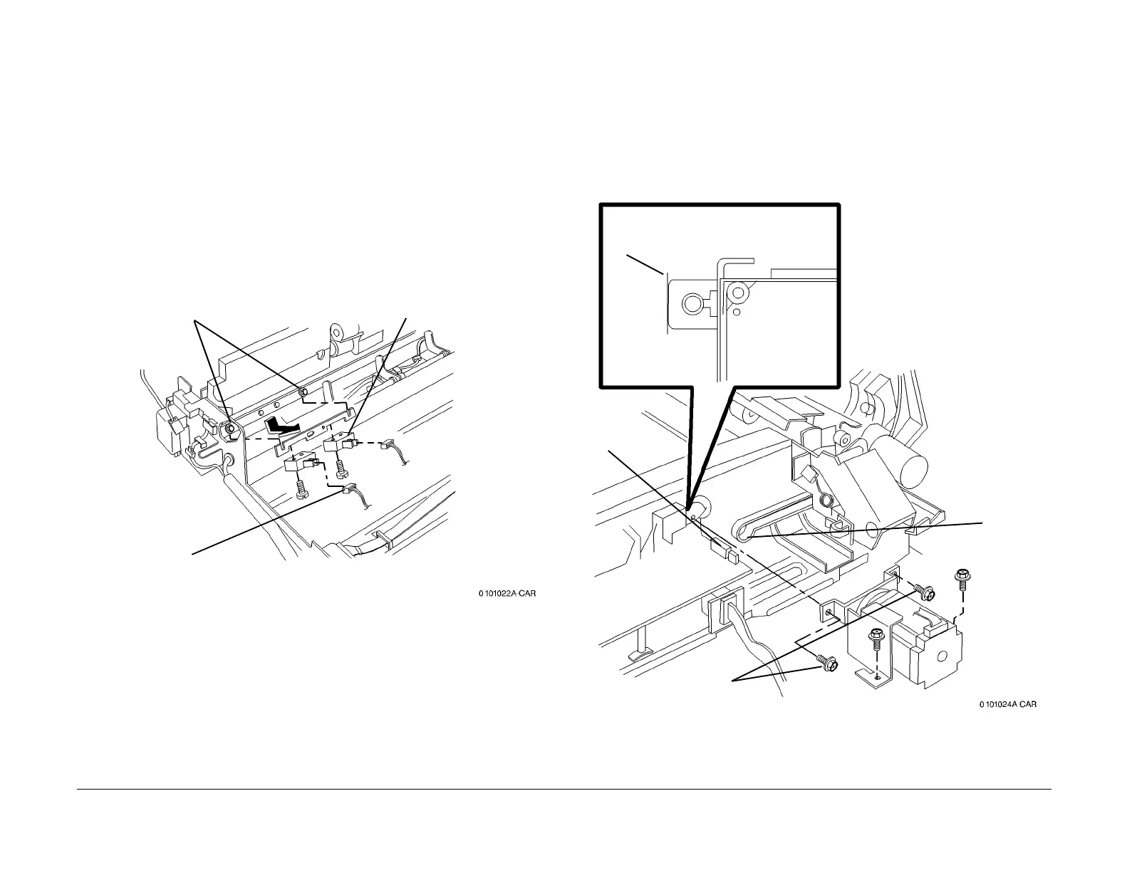
6. Remove Size Sensors 1/2 (Figure 1).
Figure 1 Removing Size Sensors 1/2
REP 5.13 DADF Belt Motor Assembly
Parts List on PL 20.6
Removal
WARNING
To avoid personal injury or shock, do not perform repair or adjustment activities with
the power switch on or electrical power applied to the machine.
1. Remove Rear Cover (REP 5.18).
2. Remove DADF Belt Motor Assembly (Figure 1).
Figure 1 Removing DADF Belt Motor Assembly
Replacement
Align motor bracket with marks on frame before tightening screws.
1
Remove
screws (2)
2
Disconnect connectors
3
Remove screws (2) and
sensors
1
Mark position of motor bracket on frame
near all four mounting screws
2
Disconnect
connector
3
Loosen
screws (4)
4
Remove
Belt from
motor pulley
and remove
motor

 Loading...


