09/03
2-129
DC 3535/2240/1632, WC M24
7-120
Status Indicator RAPs
Initial issue
7-120 Tray 4 Misfeed (3TM)
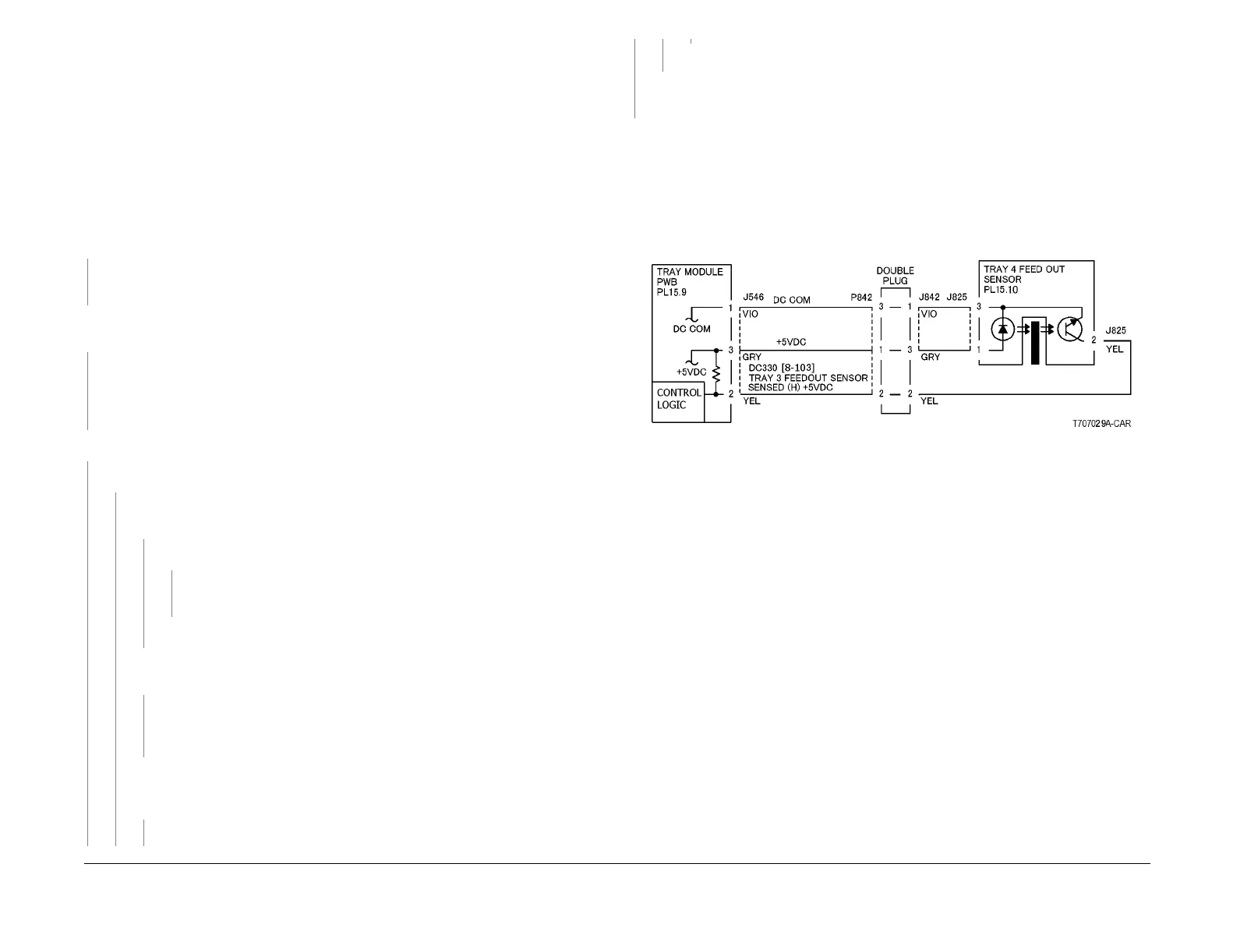
The Tray 4 Feed Out Sensor does not detect paper after feeding from Tray 4.
Initial Actions
• Check condition and specification of paper in Tray 4.
• Check the paper path for obstructions.
• Check for wear and clean the Tray 4 Feeder Roll, Takeaway Roll and Pinch Roll.
Procedure
Open the Left Cover and cheat the Left Cover Interlock Switch (PL 15.10). Enter dC330 [008-
103] and press Start. Block and unblock the Tray 4 Feed Out Sensor (PL 15.10). The dis-
play changes.
YN
Press Stop. Check the circuit of the Tray 4 Feed Out Sensor (Figure 1). Refer to the OF
99-2 RAP for troubleshooting procedure.
Press Stop. Enter dC330 [008-007] and press Start. The Tray 4 Feed/Lift Motor (PL 15.7)
energizes.
YN
Press Stop. Check the circuit of the Tray 4 Feed/Lift Motor (Figure 2). Check the wires
from the Tray Module PWB to the Tray 4 Feed/Lift Motor for an open circuit. If the wires
are good, replace the Tray 4 Feed/Lift Motor (PL 15.7). If the problem still exits, replace
the Tray Module PWB (PL 15.9).
Press Stop. Enter dC330 [008-028] and press Start. All 3 Takeaway Rolls (PL 15.10) rotate.
YN
Takeaway Motor 1 (PL 15.9) energizes.
YN
Press Stop. +24 VDC is measured between P/J552-3 and GND on the Tray
Module PWB.
YN
+24 VDC is measured at P/J555-3 on the Tray Module PWB.
YN
Refer to the +24 VDC Wirenets (Figure 5). Check the +24 VDC to the Tray
Module PWB.
Replace the Tray Module PWB (PL 15.9).
+24 VDC is measured at each of the following pins on P/J552: Pin 1, 2, 5, and
6.
YN
Refer to Figure 3. Check the wires from the Tray Module PWB to the Takeaway
Motor 1 for an open circuit. If the wires are good, replace the Takeaway Motor 1
(PL 15.9)
With [008-028] still entered, press Start and check that the voltage at P/J552 pins 1,
2, 5, and 6 each drop to approximately +22 VDC. The voltage at P/J552 pins 1, 2,
5, and 6 all drop to approximately +22 VDC when [008-028] is entered.
YN
Replace the Tray Module PWB (PL 15.9).
Replace the Takeaway Motor 1 (PL 15.9).
Press Stop. Check the Takeaway Motor 1 and its associated gears (PL 15.9) for damage,
contamination and misalignment.
Press Stop.
• Check the Tray 4 Feed/Lift Motor and its associated gears (PL 15.7) for damage, contam-
ination or misalignment.
• Ensure that the Tray 4 Chute (PL 15.10) is properly seated and not damaged.
• Ensure that the connectors shown in the circuit diagrams (Figure 1, Figure 2, Figure 3)
are securely connected and that wires are not damaged.
• If these checks are OK, replace the Tray Module PWB (PL 15.9).
Figure 1 7-120 RAP Circuit Diagram - Tray 4 Feed Out Sensor (3TM)
A
A
B
B
C
C

 Loading...


