09/03
2-196
DC 3535/2240/1632, WC M24
9-411
Initial issue
Status Indicator RAPs
YN
Go to the 9-381, ATC Sensor Failure RAP.
After checking that no failures are detected during normal operation, go to call closeout.
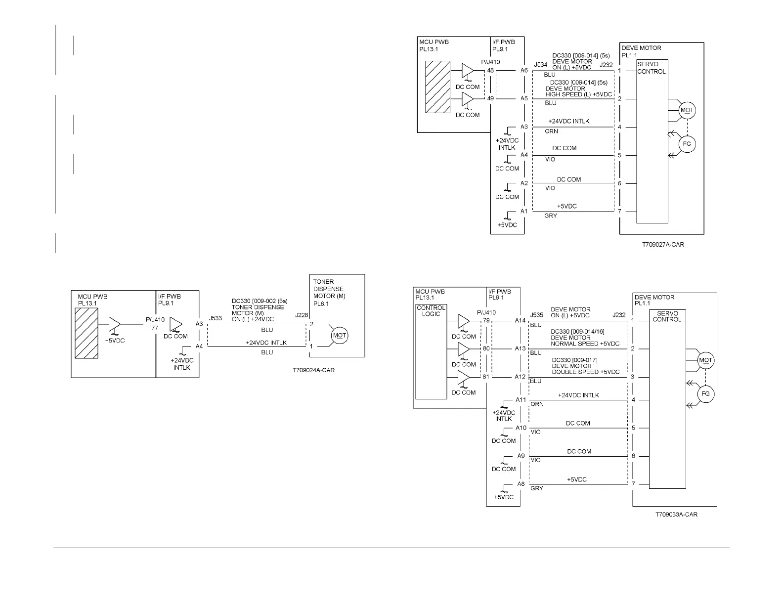
Enter dC330 [009-014] and press Start. The Developer Motor (PL 1.1) energizes.
YN
Go to Figure 3. There is +24VDC from P/J535-A11 to A10 on the I/F PWB (PL 9.1).
YN
Go to the +24VDC Wirenets (Figure 2) and troubleshoot the problem.
There is +5VDC from P/J535-A8 to A9 on the I/F PWB.
YN
Go to the +5VDC Wirenets (Figure 3) and troubleshoot the problem.
Check the wires between P/J535 on the I/F PWB and P/J232 on the Developer Motor for
opens, shorts, or loose connections. If the wires are OK, replace the Developer Motor (PL
1.1). If the problem continues, replace the MCU PWB (PL 13.1).
Check ADJ 9.3. The ATC Sensor (M) fail judgement is OK.
YN
Go to the 9-381 ATC Sensor Failure RAP.
After checking that no failures are detected during normal operation, go to call closeout.
Figure 1 9-411 Rap Circuit Diagram - Toner Dispense Motor M
Figure 2 9-411 Rap Circuit Diagram - DC2240/1632 Developer Motor
Figure 3 9-411 Rap Circuit Diagram - DC3535 Developer Motor
A

 Loading...


