09/03
2-231
DC 3535/2240/1632, WC M24
10-354
Status Indicator RAPs
Initial issue
10-354 Sub Heater Warm Up
The temperature did not reach the READY temperature.
Initial Actions
Turn off the power, remove the Fuser Assembly, and allow it to cool down.
Procedure
NOTE: If this fault is declared 3 times in succession, print and copy mode will be disabled. In
order to clear this condition, reset NVM location 744-003 to 0.
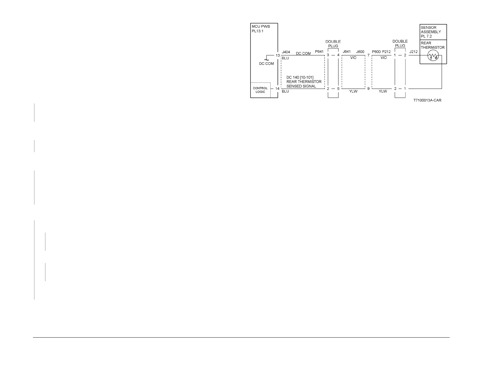
Measure the resistance between P600-7 and P600-9 on the Fuser Assembly (Figure 1). The
resistance is between 30K and 190K Ohms.
YN
Check the wiring from P600 to P/J212 for an open circuit or poor contact. If the check is
OK, replace the Sensor Assembly (PL 7.2).
Measure the resistance between P600, pins 3 and 12 on the Fuser Assembly (Figure 2). The
resistance is 20 Ohms or less.
YN
Replace the Fuser Assembly (PL 7.2).
Reinstall the Fuser Assembly, turn the power ON. Enter dC140 [010-101]. The display value
is between 678 and 699.
YN
Turn the power off. Refer to Figure 1 and check the wiring from P/J404 to J600 for an
open circuit or poor contact. If the check is OK, replace the MCU PWB (PL 13.1).
NOTE: All voltage measurements mentioned below this point must be made while the
Fuser is warming up.
Remove the Rear Cover (REP 14.2) and the cover over the 24V LVPS (3 screws). AC Line
Voltage is measured at FS47 on the AC Drive PWB (PL 9.2).
YN
+2 - 3.5VDC is measured at P/J404-7 on the MCU PWB (PL 13.1).
YN
Check the wires and connectors. If the check is OK, replace the MCU PWB (PL
13.1).
+24VDC is measured at P/J404-9 on the MCU PWB (PL 13.1).
YN
Check the wires and connectors. If the check is OK, replace the MCU PWB (PL
13.1).
Check wiring from P/J404 to P/J590 for an open circuit or poor contact. If the check is OK,
replace the AC Drive PWB.
Check the wires and connectors. If the check is OK, replace the AC Drive PWB (PL 9.2).
Figure 1 10-354 RAP Circuit Diagram - Rear Thermistor
 Loading...


