09/03
2-245
DC 3535/2240/1632, WC M24
12-106
Status Indicator RAPs
Initial issue
12-106 H Transport Exit Sensor Off
Paper did not deactuate the H Transport Exit Sensor.
Initial Actions
• Check condition and specification of the paper supply.
• Check for obstructions in the paper feed path.
• Clean the H Transport Belt and check for wear.
• Check the Guides on the H Transport Cover for damage, wear or faulty installation.
Procedure
Enter dC330 [012-104] and press Start. Open the H Transport Cover (PL 17.3) and actuate the
H Transport Exit Sensor (PL 17.4). The display changes.
YN
Press Stop. Check the circuit of the H Transport Exit Sensor (Figure 2). Refer to the OF
99-2 RAP for troubleshooting procedure.
Close the H Transport Cover and press Stop. Enter dC330 [012-001] and press Start. The
Finisher Drive Motor (PL 17.7) energizes (Figure 3).
YN
Remove the Rear Cover (PL 17.5). +24 VDC is measured between P/J879-2 and 3 on
the Finisher Drive Motor and GND.
YN
+24 VDC is measured between P/J846 -5 and 7 on the Finisher PWB and GND.
YN
Replace the Finisher PWB (PL 17.13).
Check the wires from P/J846-5 and 7 to J879-2 and 3 for damage or poor contact.
Enter dC330 [012-001] and press Start. Less than +1 VDC is measured between P/
J879 -1 on the Finisher Drive Motor and GND.
YN
Replace the Finisher Drive Motor (PL 17.7).
Check wiring between P/J879 and P/J846 for damage or poor contact. If the check is
OK, replace the Finisher PWB (PL 17.13).
Press Stop. Remove the Rear Cover (PL 17.5). Enter dC330 [012-217] and press Start. Actu-
ate the Decurler Cam Home Sensor (PL 17.8) (Figure 1). The display changes.
YN
Press Stop. Check the circuit of the Decurler Cam Home Sensor (Figure 4). Refer to the
OF 99-2 RAP for troubleshooting procedure.
Press Stop. Enter dC330 [012-070] and press Start. The Decurler Cam Clutch (PL 17.7)
momentarily energizes.
YN
Press Stop. Check the circuit of the Decurler Cam Clutch (Figure 5). Refer to OF 99-4
RAP for troubleshooting procedure.
Press Stop.
• Ensure that the connectors shown in the circuit diagrams (Figure 4, Figure 5, Figure 4,
Figure 5) are securely connected and that the wires are not damaged.
• Check the H Transport and Finisher for a docking failure (PL 17.1).
• Check the Finisher Drive Motor and its associated gears and belts (PL 17.4, PL 17.7) for
damage, contamination or misalignment.
• Decurler Roll/Pinch Roll for a drive failure (PL 17.7).
• Compiler Entrance Roll for a drive failure (PL 17.10, PL 17.12).
• Replace the H Transport Exit Sensor (PL 17.4).
• If the problem persists, replace the Finisher PWB (PL 17.13) (Figure 6).
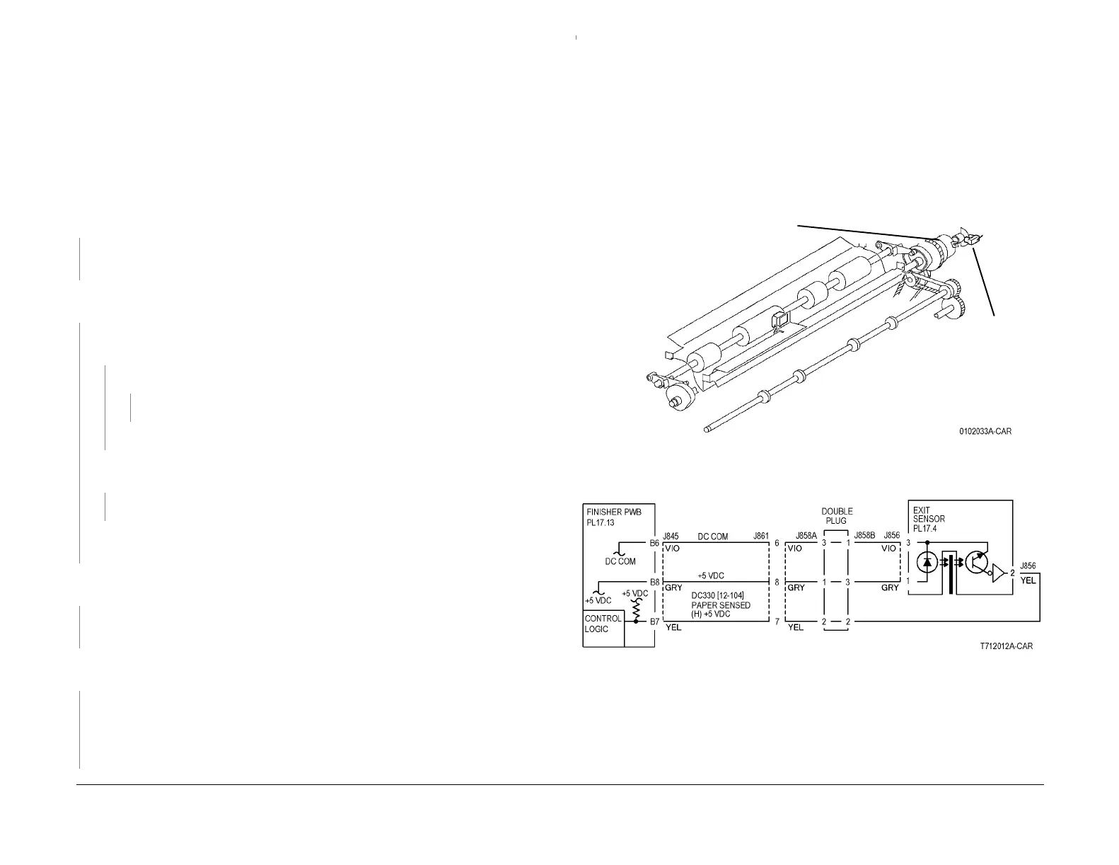
Figure 1 Component Location
Figure 2 12-106 RAP Circuit Diagram - H Transport Exit Sensor
Decurler
Clutch
Decurler
Cam
Home
Sensor
A
A
 Loading...


