09/03
2-255
DC 3535/2240/1632, WC M24
12-244
Status Indicator RAPs
Initial issue
12-244 Staple Home Sensor
The Staple Head Home Sensor did not actuate after the Stapler Motor energized to open the
Stapler.
Procedure
Enter dC330 [012-207] and press Start. Turn the Staple Motor Gear manually to actuate the
Staple Head Home Sensor. The display changes.
YN
+5 VDC is measured at Stapler Assembly between P/J886-5 and P/J886-1.
YN
+5 VDC is measured at the Finisher PWB between P/J852-1 and P/J852-5.
YN
Replace the Finisher PWB (PL 17.13) (Figure 4).
Check the wire between the Finisher PWB P/J852 and the Stapler Assembly P/
J886 for an open circuit or poor contact.
Turn the Staple Motor Gear manually to deactuate and actuate the Staple Head Home
Sensor. The voltage changes between the Stapler P/J886-4 and Finisher Frame.
YN
Switch off the power. Disconnect P/J852 on the Finisher PWB. Switch the power
on. +5 VDC is measured at the Finisher PWB P852-2.
YN
Replace the Finisher PWB (PL 17.13).
Check the wires between the Finisher P/J852 and the Stapler Assembly P/J886 for
obvious damage (Figure 2).
If the wires are good, replace the Stapler Assembly (PL 17.9).
Replace the Finisher PWB (PL 17.13).
Position paper in stapler (Figure 1). Enter dC330 [012-020] and press Start. The Staple
Motor (PL 17.9) energizes (Figure 3).
YN
With [012-020] running, +24 VDC is measured at the Finisher PWB P/J847-7.
YN
Replace the Finisher PWB (PL 17.13).
Check continuity between:
• The Finisher PWB P/J847-7 and Stapler Assembly P/J887-1
• The Finisher PWB P/J847-8 and Stapler Assembly P/J887-2
• The Finisher PWB P/J847-9 and Stapler Assembly P/J887-3
• The Finisher PWB P/J847-10 and Stapler Assembly P/J887-4
If no problems are found, replace the Stapler Assembly (PL 17.9).
If the problem continues, replace the Finisher PWB (PL 17.13).
Replace the Finisher PWB (PL 17.13).
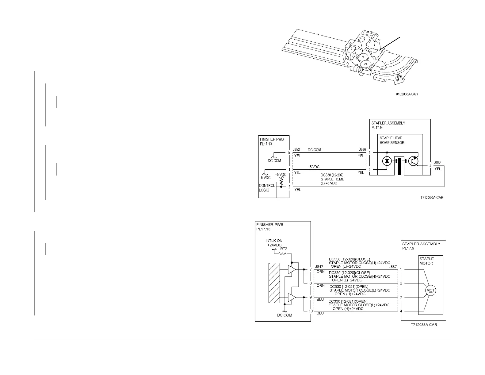
Figure 1 Component Location
Figure 2 12-244 RAP Circuit Diagram - Staple Head Home Sensor
Figure 3 12-244 RAP Circuit Diagram - Staple Motor
Stapler
Assembly
 Loading...


