09/03
2-257
DC 3535/2240/1632, WC M24
12-252
Status Indicator RAPs
Initial issue
12-252 Front Tamper
• With the Front Tamper Home Sensor off the Front Tamper Home Sensor did not turn on
after move to the Front Tamper Home position began.
• With the Front Tamper Home Sensor on, the Front Tamper Sensor did not turn off when
the Front Tamper Home Sensor deactuates.
Initial Actions
Check for obstructions in the Compiler Tray Assembly.
Procedure
Enter dC330 [012-091] (front) or [12-094] (rear) and press Start. The Front Tamper (PL
17.10) moves.
YN
The Front Tamper Motor (Figure 3) energized.
YN
Press Stop. Remove the Rear Cover (PL 17.5). +24 VDC is measured between P/
J848- B8 and B11 and GND.
YN
Replace the Finisher PWB (PL 17.13).
+24 VDC is measured between P/J848- B7, B9, B10 and B12 and GND.
YN
Check wiring between P/J848 and P/J877 for damage or poor contact. If the
check is OK, replace the Front Tamper Motor (PL 17.10).
Replace the Finisher PWB (PL 17.13).
Check the Front Tamper Motor and its associated gear and rack mechanism (PL 17.10)
for load or drive transmission failure (gear wear or breakage). Repair or replace as
required.
Press Stop. Enter dC330 [012-216] and press Start. Open the Top Cover (PL 17.6) and move
the Front Tamper manually to actuate the Front Tamper Home Sensor (PL 17.10). The dis-
play changes.
YN
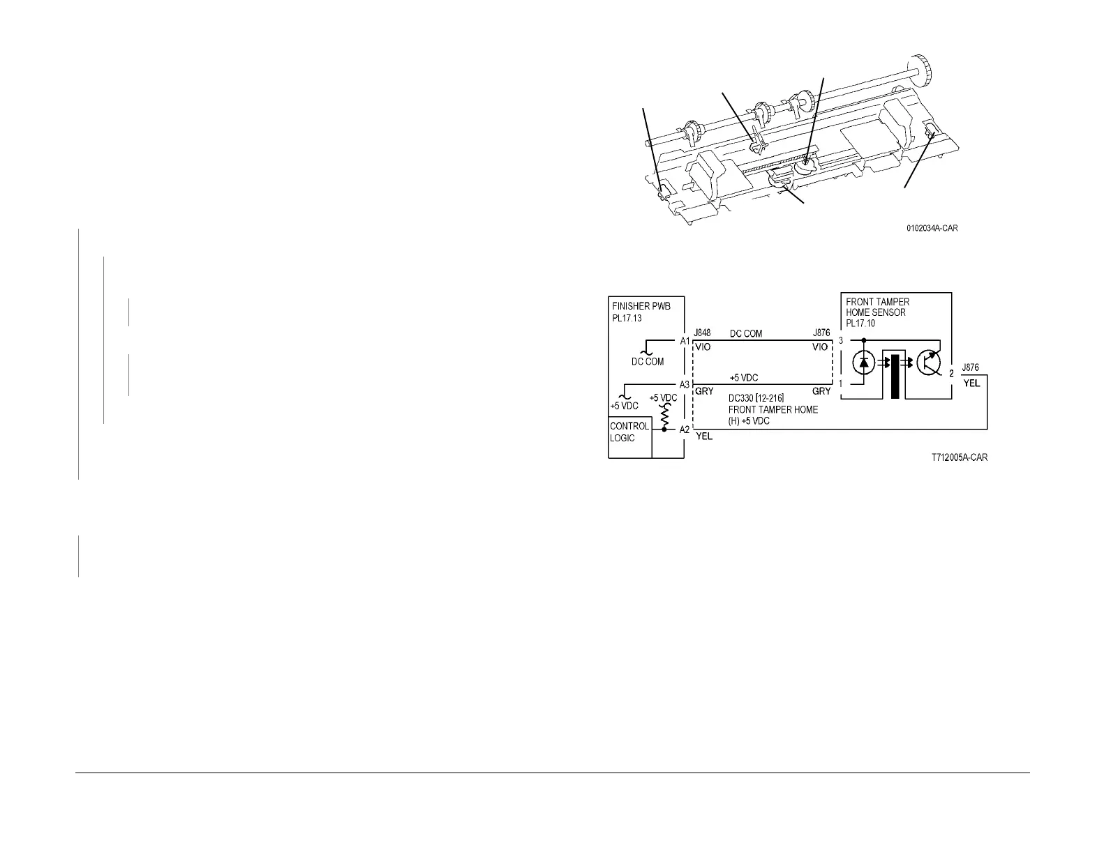
Press Stop. Check the circuit of the Front Tamper Home Sensor (Figure 2). Refer to the
OF 99-2 RAP for troubleshooting procedure.
Press Stop.
• Ensure that the connectors shown in the circuit diagrams (Figure 2, Figure 3) are securely
connected and that the wires are not damaged.
• Replace the Front Tamper Home Sensor (PL 17.10).
• If the problem persists, replace the Finisher PWB (PL 17.13) (Figure 4).
Figure 1 Component Location
Figure 2 12-252 RAP Circuit Diagram - Front Tamper Home Sensor
Rear Tamper
Home Sensor
Front
Tamper
Home
Sensor
Front Tamper Motor
Connection
Rear Tamper Motor
Connection
Compiler
Paper
Sensor
 Loading...


