09/03
2-261
DC 3535/2240/1632, WC M24
12-254
Status Indicator RAPs
Initial issue
12-254 Stacker Tray
• The Stack Height Sensor did not detect that the tray went down after the Stacker Tray
lowered at initialization.
• The Stack Height Sensor did not detect that the tray went up after the Stacker Motor was
energized.
Initial Actions
• Make sure that P/J 800 between the IOT and Finisher is securely connected.
• Check the Stack Height Sensor Actuator for disengagement, bending, obstruction and
breakage (Figure 1). Ensure that the return spring for the actuator is in place.
• Check the Stacker Tray for dragging and incorrect installation.
Procedure
Release the Stacker Drive (REP 12.20) and manually move the Stacker Tray up and down.
The Stacker Tray slides smoothly up and down without obstruction.
YN
Check the Stacker Tray belts and pulleys (PL 17.11) for damage, contamination or mis-
alignment. Repair or replace as required.
Enter dC330 [012-201] and press Start. Actuate the Stack Height Sensor (PL 17.6). The dis-
play changes.
YN
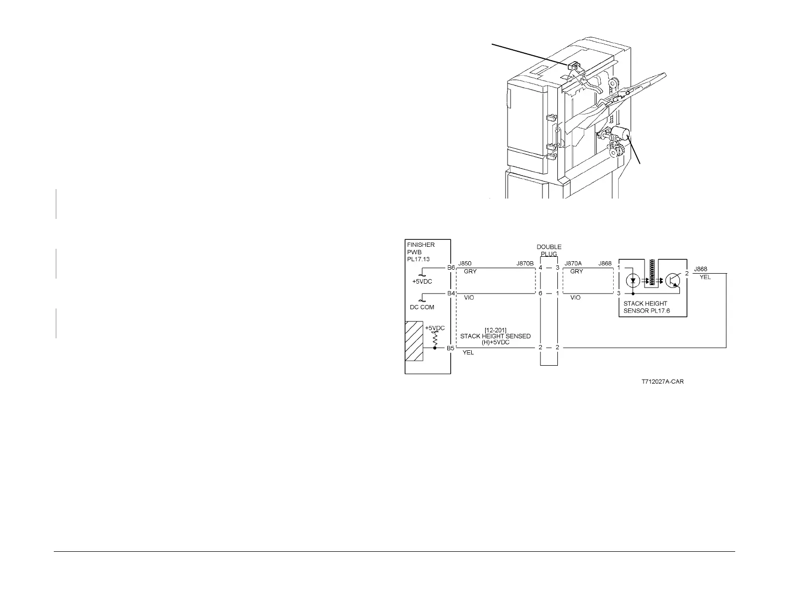
Press Stop. Check the circuit of the Stack Height Sensor (Figure 2). Refer to the OF 99-2
RAP for troubleshooting procedure.
Press Stop. Enter dC330 [012-050] (up) or [012-051] (down) and press Start. The Stacker
Motor (PL 17.11) energizes.
YN
Press Stop. Check the circuit of the Stacker Motor (Figure 3). Refer to the OF 99-6 RAP
for troubleshooting procedure.
Press Stop.
• Ensure that the connectors shown in the circuit diagrams (Figure 2, Figure 3) are securely
connected and that the wires are not damaged.
• Check the Stacker Motor and its associated gears, pulleys and belts (PL 17.11) for dam-
age, contamination or misalignment.
• Replace the Stack Height Sensor (PL 17.6).
• If the problem persists, replace the Finisher PWB (PL 17.13) (Figure 4).
Figure 1 Component Location
Figure 2 12-254 RAP Circuit Diagram - Stack Height Sensor
Stack
Height
Sensor
Stacker
Motor
 Loading...


