09/03
2-269
DC 3535/2240/1632, WC M24
12-260
Status Indicator RAPs
Initial issue
12-260 Eject Clamp Home Sensor On
The Eject Clamp Home Sensor does not turn on after the Eject Clamp up started.
Initial Actions
• Check for obstructions in the Clamp area.
Procedure
Remove the Rear Cover (PL 17.5) and the Eject Clamp Home Sensor bracket (PL 17.8) (leave
sensor connected). Enter dC330 [012-210] and press Start. Actuate the Eject Clamp Home
Sensor (PL 17.8) (Figure 1). The display changes.
YN
Press Stop. Check the circuit of the Eject Clamp Home Sensor (Figure 2). Refer to the
OF 99-2 RAP for troubleshooting procedure.
Restore mounting of the Eject Clamp Home Sensor. Enter dC330 [012-034] and press Start.
The Eject Clamp (PL 17.6) moves up.
YN
The Eject Motor (Figure 3) energized.
YN
Remove the Rear Cover (PL 17.5). +24 VDC is measured between P/J881- 2 and
5 on the Eject Motor and GND.
YN
+24 VDC is measured between P/J846- 6 and 12 on the Finisher PWB and
GND.
YN
Replace the Finisher PWB (PL 17.13).
Check wiring between P/J846- 6 and 12 and P/J881- 2 and 5 for damage or
poor contact.
+24 VDC is measured between P/J881- 1, 3, 4 and 6 on the Eject Motor and
GND.
YN
Replace the Eject Motor (PL 17.8).
Check the wires from P/J846 to P/J881 for damage or poor contact. If the check is
OK, replace the Finisher PWB (PL 17.13).
Check the Eject Motor and its associated gears, pulleys and belts (PL 17.8) for damage,
contamination and misalignment.
Press Stop.
• Ensure that the connectors shown in the circuit diagrams (Figure 2, Figure 3) are securely
connected and that the wires are not damaged.
• Replace the Eject Clamp Home Sensor (PL 17.8).
• If the problem persists, replace the Finisher PWB (PL 17.13) (Figure 4).
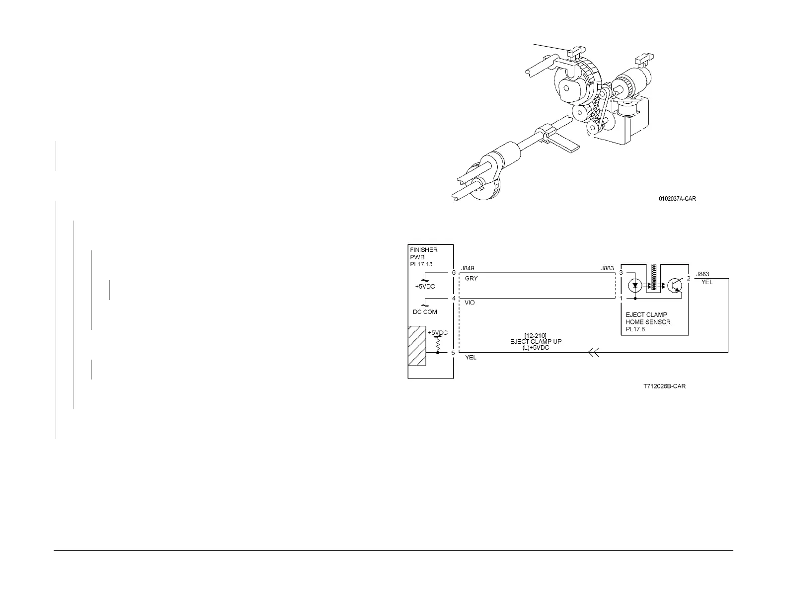
Figure 1 Component Location
Figure 2 12-260 RAP Circuit Diagram - Eject Clamp Home Sensor
Eject Clamp Home Sensor

 Loading...


