09/03
2-697
DC 3535/2240/1632, WC M24
OF 1-1, OF 1-2
Status Indicator RAPs
Initial issue
OF 1-1 +3.3 VDC
Use this RAP to troubleshoot a failure with the +3.3 VDC.
Procedure
Perform the following:
• Remove the Rear Cover (REP 14.2).
• Tilt out the HVPS Chassis (REP 1.6).
Check that power is switched off. Measure the resistance of the fuse on the +3.3V LVPS (Fig-
ure 1). The resistance is 1 ohm or less.
YN
Replace the +3.3V LVPS (PL 9.1).
Disconnect P/J510 on the 3.3V LVPS. Switch on the power. Measure the AC voltage between
the white and black wires in P/J15A on the +3.3V LVPS (Figure 1). AC Line Voltage is mea-
sured.
YN
Go to OF 1-4.
Connect the black meter lead to ground. Measure the DC voltage at P/J510 on the +3.3 V
LVPS (Figure 1). Voltages are measured as shown (Figure 1).
YN
Replace the 3.3V LVPS (PL 9.1).
There is a short circuit in +3.3 VDC distribution.
Refer to Section 7 wirenets for +3.3 VDC distribution.
Disconnect the P/J’s in the distribution network. Switch the power on. Connect the P/J’s while
monitoring +3.3 VDC. The +3.3 VDC supply will shut down when the P/J with the shorted cir-
cuit is connected.
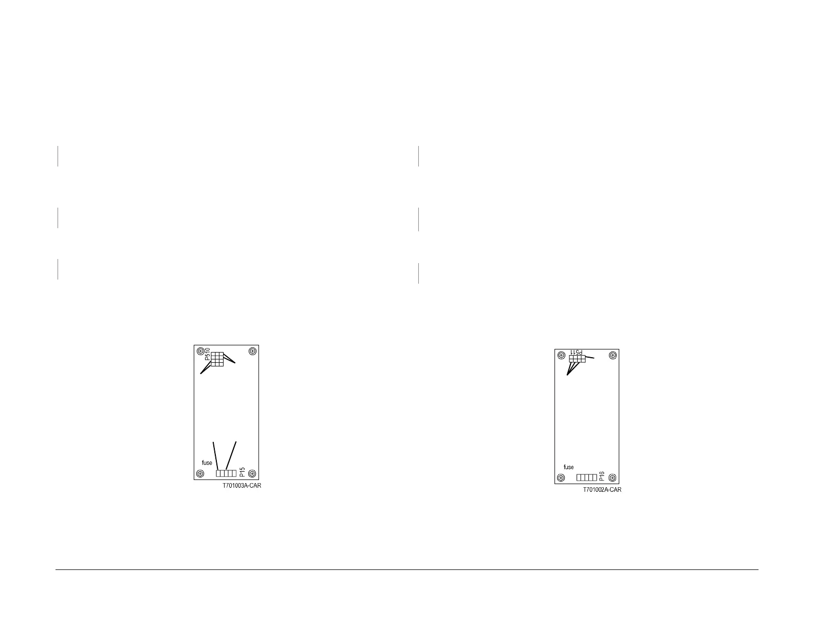
Figure 1 P15, P510 on +3.3V LVPS
OF 1-2 +5 VDC
Use this RAP to troubleshoot a failure with the +5 VDC.
Procedure
Perform the following:
• Remove the Rear Cover (REP 14.2).
• Tilt out the HVPS Chassis (REP 1.6).
Check that power is switched off. Measure the resistance of the fuse on the +5V LVPS (Figure
1). The resistance is 1 ohm or less.
YN
Replace the +5V LVPS (PL 9.1).
Disconnect P/J511 on the +5V LVPS. Switch on the power. Measure the AC voltage between
the black and white wires in P/J16 on the +5V LVPS (Figure 1). AC Line Voltage is mea-
sured.
YN
Go to OF 1-4.
Connect the black meter lead to ground. Measure the DC voltage at P/J511 on the +5V LVPS
(Figure 1). Voltages are measured as shown.
YN
Replace the +5V LVPS (PL 9.1).
There is a short circuit in +5 VDC distribution.
Refer to Section 7 wirenets for +5 VDC distribution.
Disconnect the P/J’s in the distribution network. Switch the power on. Connect the P/J’s while
monitoring +5 VDC. The +5 VDC supply will shut down when the P/J with the shorted circuit is
connected.
Figure 1 P16, P511 on +5V LVPS
+3.3
VDC
RET
Vio
+3.3
VDC
GRY (6)
Black
Wire
White
Wire
+5VDC
RET
Vio (all)
+5VDC
GRY

 Loading...


