09/03
2-705
DC 3535/2240/1632, WC M24
OF 99-1
Status Indicator RAPs
Initial issue
OF 99-1 Reflective Sensor RAP
Sensors consist of a light-emitting diode and a photo transistor. When energized, the light from
the LED causes the photo transistor to conduct, drawing current through a pull-up resistor. The
voltage drop across the resistor causes the input signal to the control logic to change from a
high to a low.
Reflective sensors operate by light from the LED being reflected off the paper to the photo tran-
sistor, causing the output of the sensor to go to the low (L) state.
Initial Actions
Ensure that the sensor is not actuated.
Procedure
Enter the component control code indicated in the Procedure and/or Circuit Diagram of the
RAP that sent you here. Actuate the sensor using a sheet of paper. The display changes
with each actuation.
YN
Clean the sensor and then block and unblock it. The display changes with each actua-
tion.
YN
Access to some sensors in this machine is difficult. Follow the Y leg if you can
access the sensor connector. Follow the N leg if access is not possible. The sen-
sor connector is accessible.
YN
Check the voltage at the output of the PWB or power supply (refer to the Circuit
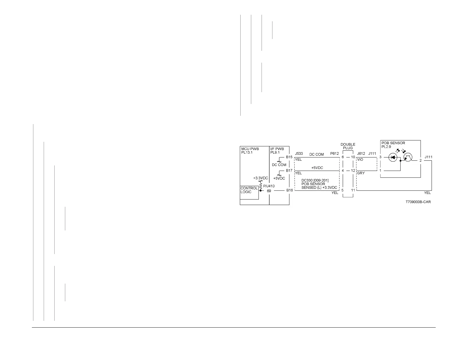
Diagram). In the example for this generic procedure (Figure 1), voltage is pro-
vided from J533 on the I/F PWB. Check for pull-up voltage for the output signal.
This voltage will be either +5 VDC or +3.3 VDC depending on the circuit (refer
to the Circuit Diagram for the correct voltage). The voltage corresponds with
the voltage shown in the Circuit Diagram.
YN
Check for short circuit(s) that may be loading down the line. Check the
power input to the PWB(s). If this does not resolve the problem, replace
the PWB.
Refer to the Circuit Diagram. Check the wires from the PWB to the sensor for
opens, shorts, or loose contacts. If the wires are OK, replace the sensor. If this
does not resolve the problem, replace the PWB
The display indicates a constant L.
YN
Check for +5VDC to the sensor (typically pins 1 and 3 on a 3 pin connec-
tor). +5 VDC is present.
YN
Use the circuit diagram and/or the wirenets in Section 7 to trace the prob-
lem.
Disconnect the sensor. Use a jumper wire to connect the output wire from the
sensor (typically pin 2 on a 3 pin connector) to DC COM or GND. The display
changes from H to L.
YN
There is either an open circuit or a failed PWB. Use the Circuit Diagram to
trace the output wire to the PWB. If the wire is OK, replace the PWB.
Replace the sensor.
Disconnect the sensor. The display indicates H.
YN
When sensors are unplugged, the input at the PWB should always be high if
there is no harness short or PWB failure. Check the output wire from the sensor
(typically pin 2 on a 3 pin connector) to the PWB for a short circuit. If the wire is
good, replace the PWB. Figure 1 represents a typical sensor for this machine.
The sensor is shorted. Replace the sensor.
Look for unusual sources of contamination.
The sensor and the circuit appear to operate normally. Check the adjustment of the sensor.
Clean the sensor. Check for intermittent connections, shorted, or open wires. If the problem
continues, replace the sensor.
Figure 1 OF 99-1 RAP Circuit Diagram - Typical Reflective Sensor
A
A
B
B
C
C

 Loading...


