09/03
2-60
DC 3535/2240/1632, WC M24
4-341
Initial issue
Status Indicator RAPs
4-341 IOT Logic Failure
MCU PWB cannot detect INTLK +5 VDC.
Initial Actions
• Check that the Waste Toner Bottle and all four Drum Cartridges are seated correctly.
• Check fault history for 9-925 faults. If this fault has occurred recently, go to the 9-925 RAP.
• Check that the I/F PWB is securely connected to the MCU PWB at P410.
• Reinstall the IOT software. Refer to the instructions on the s/w install CD.
Procedure
There is +5VDC from P/J535-B13 on the I/F PWB to GND.
YN
There is +5VDC from P/J631-1 to GND.
YN
There is +5VDC from P/J631-3 to GND.
YN
Go to Figure 1. Check the wire from FS134 to P/J631-3 for an open circuit.
Go to Figure 1. Check the +5VDC INTLK wiring through the Drum connectors ( P/
J151 - P/J154). If the wires are OK, check the CRUM connectors on the Drum Car-
tridges for damage, wear, or contamination. Clean, repair, or replace as required
(Machine Consumables) (PL 4.1).
Go to Figure 1. Check for an open circuit between P/J631-1 and P/J568-2 on the Inter-
lock Relay PWB (PL 9.1). If this wire is OK, check for an open circuit between P/J535-
B13 and P/J568-1. If this wire is OK, replace the Interlock Relay PWB (PL 9.1).
There is +5VDC from P/J401-B20 to GND.
YN
There is +5VDC from P/J400-9 to GND.
YN
Go to Figure 1. Check the wire from J568-5 to J400 -9 for an open circuit. If the wire
is OK, replace the Interlock Relay PWB (PL 9.1).
Go to Figure 1. Check the four wires from J401 to P/J526 - P/J529 on the ROS for a
short circuit. If the wires are OK, replace the MCU PWB (PL 13.1). If the problem contin-
ues, replace the ROS (PL 3.1).
Go to Figure 1. Check the wires between the MCU PWB and the ROS for an open circuit or
loose connection:
• J401-A1 to J527-1
• J401-A2 to J526-1
• J401-B19 to J528-1
• J401-B20 to J529-1
If the wires are OK, replace the MCU PWB (PL 13.1). If the problem continues, replace the
ROS (PL 3.1).
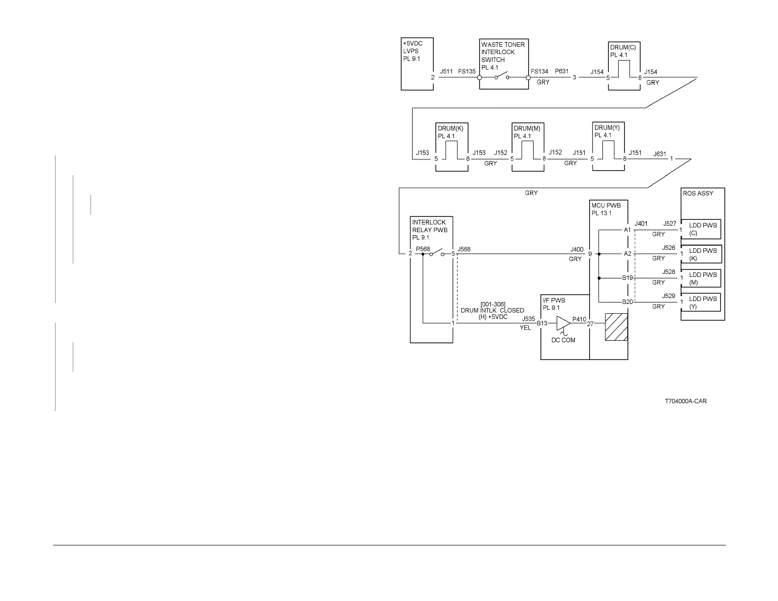
Figure 1 4-341 RAP Circuit Diagram

 Loading...


