RM0367 Rev 7 135/1043
RM0367 Firewall (FW)
141
Below is the initialization procedure to follow:
1. Configure the RCC to enable the clock to the Firewall module
2. Configure the RCC to enable the clock of the system configuration registers
3. Set the base address and length of each segment (CSSA, CSL, NVDSSA, NVDSL,
VDSSA, VDSL registers)
4. Set the configuration register of the Firewall (FW_CR register)
5. Enable the Firewall clearing the FWDIS bit in the system configuration register.
The Firewall configuration register (FW_CR register) is the only one which can be managed
in a dynamic way even if the Firewall is enabled:
• when the Non-Volatile data segment is undefined (meaning the NVDSL register is
equal to 0), the accesses to this register are possible whatever the Firewall state
(opened or closed).
• when the Non-Volatile data segment is defined (meaning the NVDSL register is
different from 0), the accesses to this register are only possible when the Firewall is
opened.
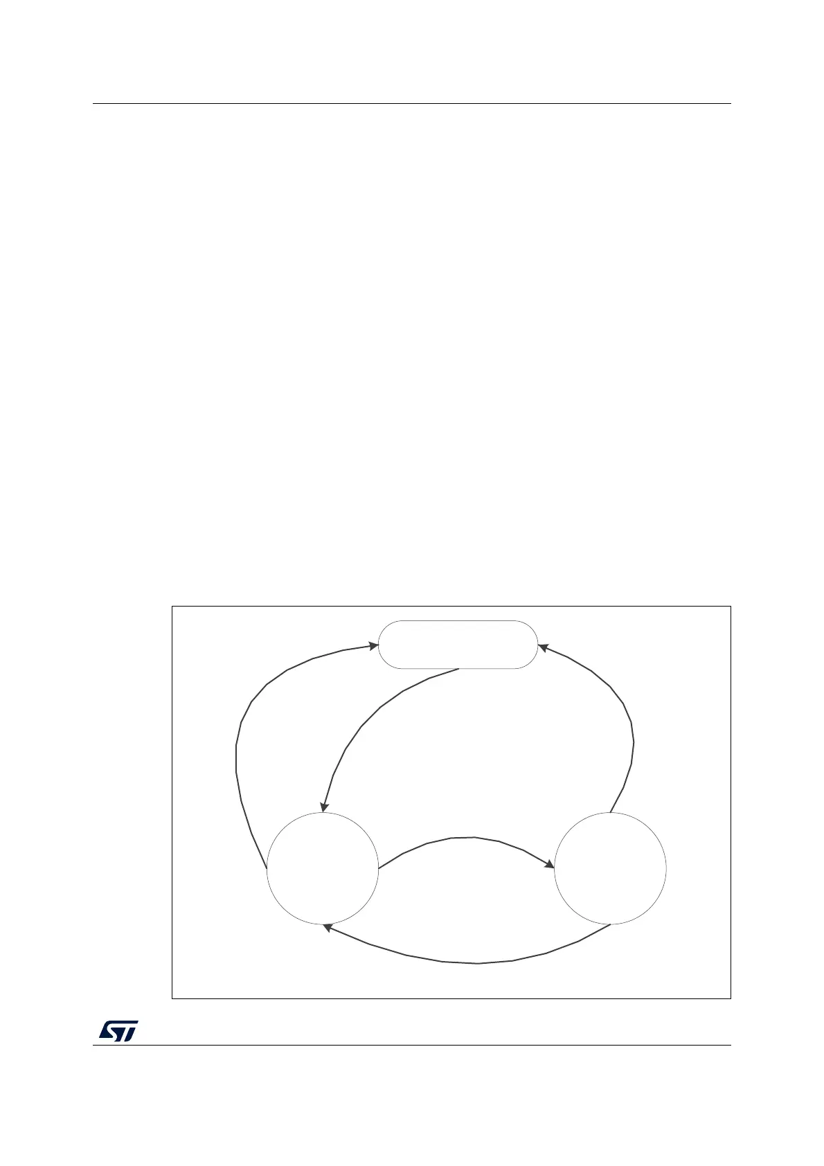
5.3.6 Firewall states
The Firewall has three different states as shown in Figure 9:
• Disabled: The FWDIS bit is set by default after the reset. The Firewall is not active.
• Closed: The Firewall protects the accesses to the three segments (Code, Non-volatile
data, and Volatile data segments).
• Opened: The Firewall allows access to the protected segments as defined in
Section 5.3.4: Segment accesses and properties.
Figure 9. Firewall functional states
MS32390V4
Firewall disable
(reset)
Firewall
closed
Firewall
opened
Enable the firewall
(FWDIS = 0)
‘‘call gate’’ entry
Illegal accesses to
the protected
segments
Code protected jumps
to unprotected
segments
Protected code jumps
to an unprotected
segment and FPA = 0
 Loading...


