Power control (PWR) RM0367
154/1043 RM0367 Rev 7
6.3.1 Behavior of clocks in low-power modes
APB peripheral and DMA clocks can be disabled by software.
Sleep and Low-power sleep modes
The CPU clock is stopped in Sleep and Low-power sleep mode. The memory interface
clocks (Flash memory and RAM interfaces) and all peripherals clocks can be stopped by
software during Sleep. The memory interface clock is stopped and the RAM is in power-
down when in Low-power sleep mode. The AHB to APB bridge clocks are disabled by
hardware during Sleep/Low-power sleep mode when all the clocks of the peripherals
connected to them are disabled.
Stop and Standby modes
The system clock and all high speed clocks are stopped in Stop and Standby modes:
• PLL is disabled
• Internal RC 16 MHz (HSI16) oscillator is disabled
• External 1-24 MHz (HSE) oscillator is disabled
• Internal 65 kHz - 4.2 MHz (MSI) oscillator is disabled
When exiting this mode by an interrupt (Stop mode), the internal MSI or HSI16 can be
selected as system clock. For both oscillators, their respective configuration (range and
trimming) value is kept on Stop mode exit.
When exiting this mode by a reset (Standby mode), the internal MSI oscillator is selected as
system clock. The range and the trimming value are reset to the default 2.1 MHz.
If a Flash program operation or an access to APB domain is ongoing, the Stop/Standby
mode entry is delayed until the Flash memory or the APB access has completed.
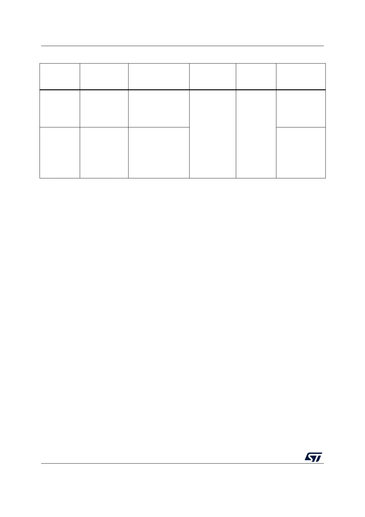
Stop
PDDS, LPSDSR
bits +
SLEEPDEEP bit +
WFI, Return from
ISR or WFE
Any EXTI line
(configured in the EXTI
registers, internal and
external lines)
All V
CORE
domain clocks
OFF
HSI16
(1)
, HSE
and MSI
oscillators
OFF
In low-power
mode
Standby
PDDS bit +
SLEEPDEEP bit +
WFI, Return from
ISR or WFE
WKUP pin rising edge,
RTC alarm (Alarm A or
Alarm B), RTC Wakeup
event, RTC tamper
event, RTC timestamp
event, external reset in
NRST pin, IWDG reset
OFF
1. HSI16 can run in Stop mode provided HSI16KERON is set in Clock control register (RCC_CR).
Table 32. Summary of low-power modes (continued)
Mode name Entry Wakeup
Effect on V
CORE
domain clocks
Effect on V
DD
domain
clocks
Voltage regulator