RM0367 Rev 7 493/1043
RM0367 General-purpose timers (TIM2/TIM3)
546
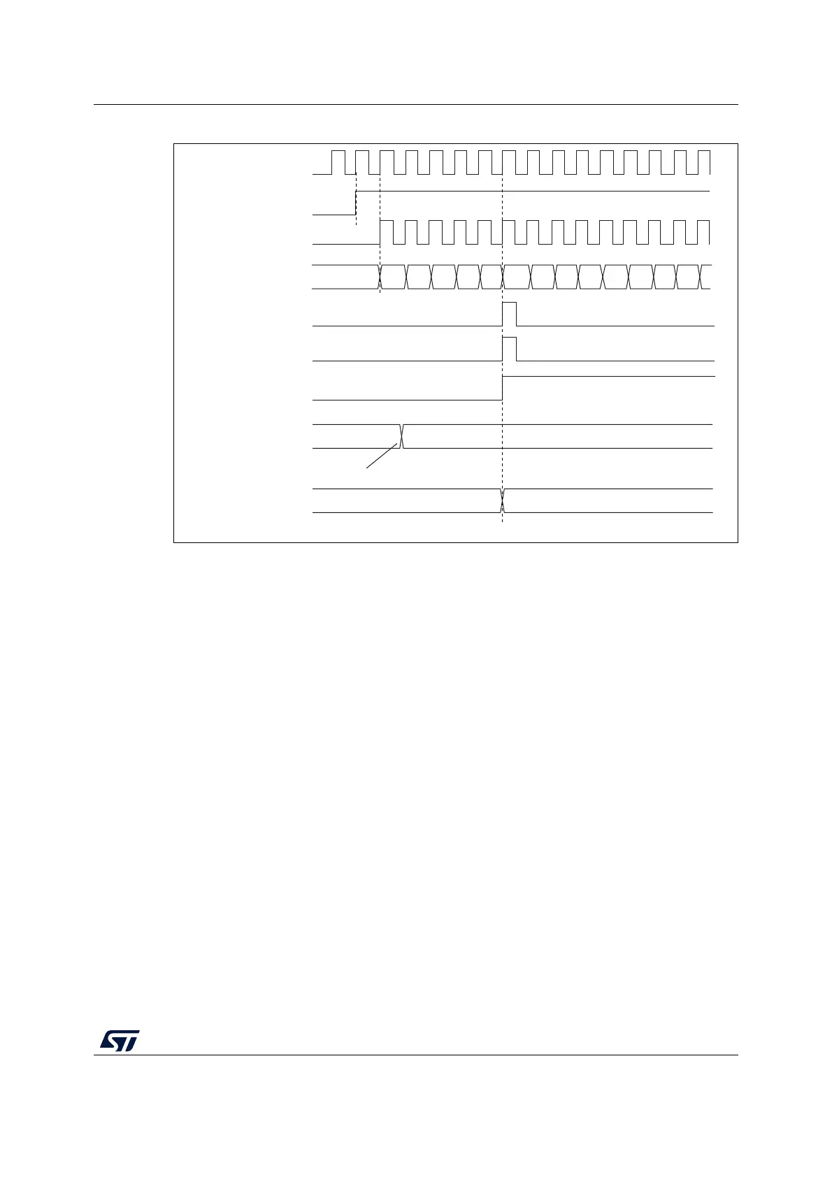
Figure 125. Counter timing diagram, Update event with ARPE=1 (counter overflow)
21.3.3 Clock selection
The counter clock can be provided by the following clock sources:
• Internal clock (CK_INT)
• External clock mode1: external input pin (TIx)
• External clock mode2: external trigger input (ETR)
• Internal trigger inputs (ITRx): using one timer as prescaler for another timer. Refer to :
Using one timer as prescaler for another timer on page 516 for more details.
Internal clock source (CK_INT)
If the slave mode controller is disabled (SMS=000 in the TIMx_SMCR register), then the
CEN, DIR (in the TIMx_CR1 register) and UG bits (in the TIMx_EGR register) are actual
control bits and can be changed only by software (except UG which remains cleared
automatically). As soon as the CEN bit is written to 1, the prescaler is clocked by the internal
clock CK_INT.
Figure 126 shows the behavior of the control circuit and the upcounter in normal mode,
without prescaler.
MS31194V1
FD
36
CK_PSC
Timer clock = CK_CNT
Counter register
Update event (UEV)
Counter overflow
Update interrupt flag
(UIF)
36
34
33 32 31
30
2F
F8
F9
FA FB
FCF7
35
CEN
Auto-reload preload
register
Write a new value in TIMx_ARR
Auto-reload active
register
FD
36
 Loading...


