RM0367 Rev 7 521/1043
RM0367 General-purpose timers (TIM2/TIM3)
546
Starting 2 timers synchronously in response to an external trigger
In this example, we set the enable of timer x when its TI1 input rises, and the enable of
Timer y with the enable of Timer x. Refer to Figure 146 for connections. To ensure the
counters are aligned, Timer x must be configured in Master/Slave mode (slave with respect
to TI1, master with respect to Timer y):
1. Configure Timer x master mode to send its Enable as trigger output (MMS=001 in the
TIMx_CR2 register).
2. Configure Timer x slave mode to get the input trigger from TI1 (TS=100 in the
TIMx_SMCR register).
3. Configure Timer x in trigger mode (SMS=110 in the TIMx_SMCR register).
4. Configure the Timer x in Master/Slave mode by writing MSM=1 (TIMx_SMCR register).
5. Configure Timer y to get the input trigger from Timer x (TS=000 in the TIMy_SMCR
register).
6. Configure Timer y in trigger mode (SMS=110 in the TIMy_SMCR register).
For code example, refer to A.11.20: Two timers synchronized by an external trigger code
example.
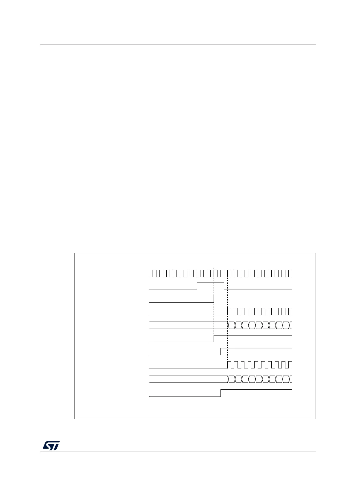
When a rising edge occurs on TI1 (Timer x), both counters starts counting synchronously on
the internal clock and both TIF flags are set.
Note: In this example both timers are initialized before starting (by setting their respective UG
bits). Both counters starts from 0, but an offset can easily be inserted between them by
writing any of the counter registers (TIMx_CNT). One can see that the master/slave mode
insert a delay between CNT_EN and CK_PSC on timer x.
Figure 151. Triggering timer x and y with timer x TI1 input
MS33141V1
CK_INT
TIMERy-CNT
TIMERx-CEN=CNT_EN
TIMERy-TIF
01
TIMERx-CNT
02 03 04 05 06 07 08 09
00
01 02 03 04 05 06 07 08 0900
TIMERy-CEN=CNT_EN
TIMERx-TIF
TIMERx-CK_PSC
TIMERx-TI1
TIMERy-CK_PSC
 Loading...


