RM0367 Rev 7 261/1043
RM0367 System configuration controller (SYSCFG)
264
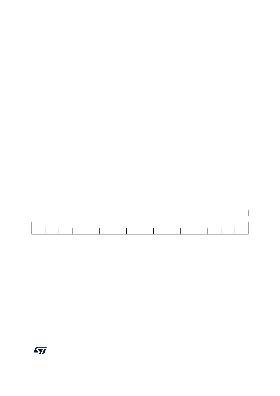
10.2.4 SYSCFG external interrupt configuration register 1
(SYSCFG_EXTICR1)
Address offset: 0x08
Reset value: 0x0000
Bits 5:4 SEL_VREF_OUT: VREFINT_ADC connection bit
These bits are set and cleared by software (only if REF_LOCK not set). These bits select
which pad is connected to VREFINT_ADC when ENBUF_VREFINT_ADC is set.
00: no pad connected
01: PB0 connected
10: PB1 connected
11: PB0 and PB1 connected
Bits 3:1 Reserved, must be kept at reset value
Bit 0 EN_VREFINT: VREFINT enable and scaler control for COMP2 enable bit
This bit is set and cleared by software (only if REF_LOCK not set). It switches on VREFINT
internal reference voltage and enables the scaler for COMP2.
0: VREFINT voltage disabled in low-power mode (if ULP=1) and scaler for COMP2 disabled
1: VREFINT voltage enabled in low-power mode and scaler for COMP2 enabled
Note: It is forbidden to configure both EN_VREFINT=1 and ULP=1 if the device is in Stop
mode or in Sleep/Low-power sleep mode (refer to Section 6.4.1: PWR power control
register (PWR_CR) for a description of the ULP bit). If the device is not in low-power
mode, VREFINT is always enabled whatever the state of EN_VREFINT and ULP.
EN_VREFINT controls only COMP2 scaler. The Scaler must be enabled to provide
V
REFINT
voltage or its fraction to COMP2 (scaler performs V
REFINT
buffering and
scaling).
31 30 29 28 27 26 25 24 23 22 21 20 19 18 17 16
Reserved
1514131211109876543210
EXTI3[3:0] EXTI2[3:0] EXTI1[3:0] EXTI0[3:0]
rw rw rw rw rw rw rw rw rw rw rw rw rw rw rw rw
Bits 31:16 Reserved
Bits 15:0 EXTIx[3:0]: EXTI x configuration (x = 0 to 3)
These bits are written by software to select the source input for the EXTIx external interrupt.
0000: PA[x] pin
0001: PB[x] pin
0010: PC[x] pin
0011: PD[x] pin
0100: PE[x] pin
0101: PH[x] (only PH[1:0] and PH[10:9])
Other configurations are reserved