RM0367 Rev 7 269/1043
RM0367 Direct memory access controller (DMA)
288
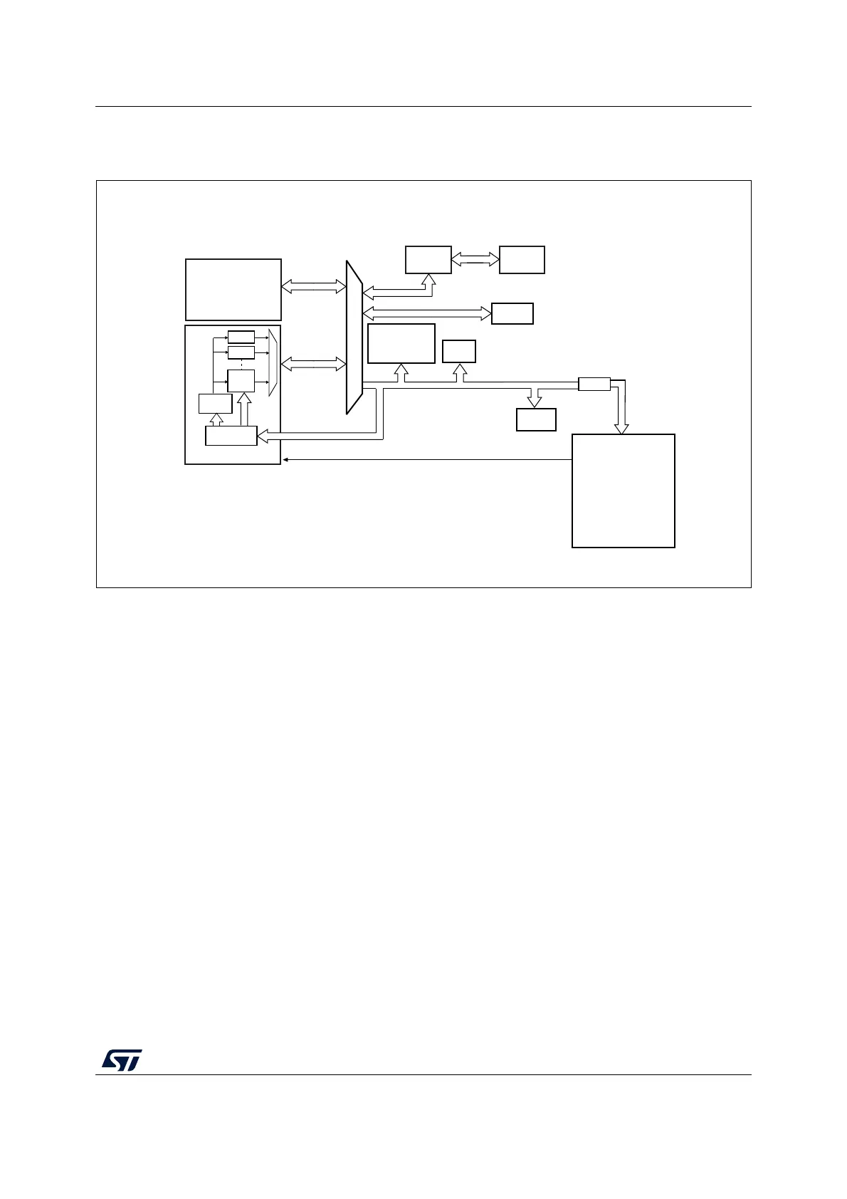
The DMA block diagram is shown in the figure below.
Figure 28. DMA block diagram
The DMA controller performs direct memory transfer by sharing the AHB system bus with
other system masters. The bus matrix implements round-robin scheduling. DMA requests
may stop the CPU access to the system bus for a number of bus cycles, when CPU and
DMA target the same destination (memory or peripheral).
According to its configuration through the AHB slave interface, the DMA controller arbitrates
between the DMA channels and their associated received requests. The DMA controller
also schedules the DMA data transfers over the single AHB port master.
The DMA controller generates an interrupt per channel to the interrupt controller.
11.4.2 DMA transfers
The software configures the DMA controller at channel level, in order to perform a block
transfer, composed of a sequence of AHB bus transfers.
A DMA block transfer may be requested from a peripheral, or triggered by the software in
case of memory-to-memory transfer.
MS32796V3
SRAM
Ch.1
Ch.2
Arbiter
Cortex-
M0+
AHB Slave
DMA
System
DMA request
APB
Bus matrix
DMA
Reset &
Clock control
(RCC)
FLITF Flash
up to
Ch.7
ADC
SPI1/SPI2
USART1/2/4/5
LPUART1
I2C1/2/3
TIM2/3/6/7
DAC2
CRC
Bridge
AES
 Loading...


