RM0367 Rev 7 333/1043
RM0367 Analog-to-digital converter (ADC)
352
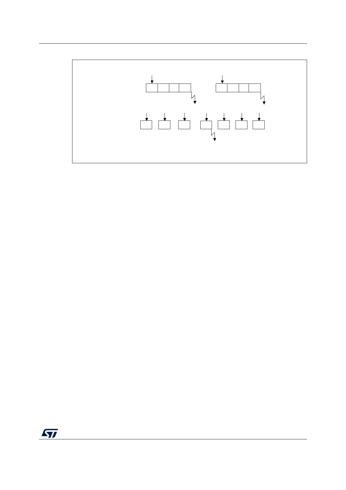
Figure 56. Triggered oversampling mode (TOVS bit = 1)
14.9 Temperature sensor and internal reference voltage
The temperature sensor can be used to measure the junction temperature (T
J
) of the
device. The temperature sensor is internally connected to the ADC V
IN
[18] input channel
which is used to convert the sensor’s output voltage to a digital value. The sampling time for
the temperature sensor analog pin must be greater than the minimum T
S_temp
value
specified in the datasheet. When not in use, the sensor can be put in power down mode.
The internal voltage reference (V
REFINT) provides a stable (bandgap) voltage output for the
ADC and comparators. V
REFINT is internally connected to the ADC V
IN
[17] input channel.
The precise voltage of V
REFINT is individually measured for each part by ST during
production test and stored in the system memory area. It is accessible in read-only mode.
Figure 57 shows the block diagram of connections between the temperature sensor, the
internal voltage reference and the ADC.
The TSEN bit must be set to enable the conversion of ADC V
IN
[18] (temperature sensor)
and the VREFEN bit must be set to enable the conversion of ADC V
IN
[17] (V
REFINT
).
The temperature sensor output voltage changes linearly with temperature. The offset of this
line varies from chip to chip due to process variation (up to 45 °C from one chip to another).
The uncalibrated internal temperature sensor is more suited for applications that detect
temperature variations instead of absolute temperatures. To improve the accuracy of the
temperature sensor measurement, calibration values are stored in system memory for each
device by ST during production.
During the manufacturing process, the calibration data of the temperature sensor and the
internal voltage reference are stored in the system memory area. The user application can
then read them and use them to improve the accuracy of the temperature sensor or the
internal reference. Refer to the datasheet for additional information.
MS33700V1
Ch(N)
0
Ch(N)
1
Ch(N)
2
Ch(N)
3
Trigger Trigger
CONT = 0
(DISCEN = 1)*
TOVS = 0
(DISCEN = 1)*: DISCEN bit is forced to 1 by software when TOVS bit is set
EOC flag set
EOC flag set
CONT = 0
(DISCEN = 1)*
TOVS = 1
Trigger
Ch(N)
0
Ch(N)
1
Ch(N)
2
Ch(N)
3
Trigger
Ch(N)
2
Trigger
Ch(N)
3
Trigger
Ch(N)
2
Trigger
Ch(N)
0
Trigger
Ch(N)
1
Trigger
Ch(N)
1
Ch(N)
0
 Loading...


