Analog-to-digital converter (ADC) RM0367
316/1043 RM0367 Rev 7
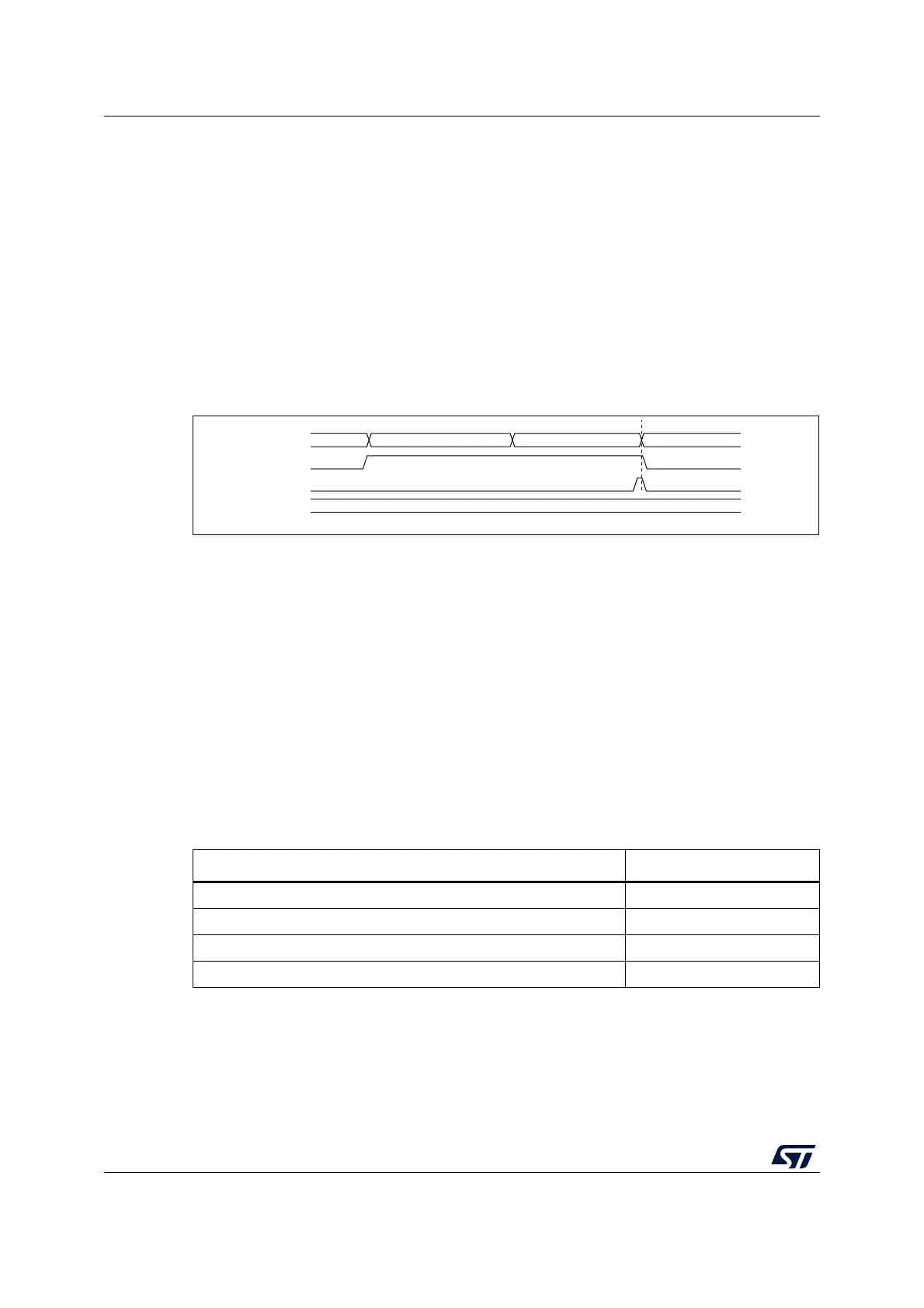
14.3.14 Stopping an ongoing conversion (ADSTP)
The software can decide to stop any ongoing conversions by setting ADSTP = 1 in the
ADC_CR register.
This resets the ADC operation and the ADC is idle, ready for a new operation.
When the ADSTP bit is set by software, any ongoing conversion is aborted and the result is
discarded (ADC_DR register is not updated with the current conversion).
The scan sequence is also aborted and reset (meaning that restarting the ADC would re-
start a new sequence).
Once this procedure is complete, the ADSTP and ADSTART bits are both cleared by
hardware and the software must wait until ADSTART=0 before starting new conversions.
Figure 39. Stopping an ongoing conversion
14.4 Conversion on external trigger and trigger polarity (EXTSEL,
EXTEN)
A conversion or a sequence of conversion can be triggered either by software or by an
external event (for example timer capture). If the EXTEN[1:0] control bits are not equal to
“0b00”, then external events are able to trigger a conversion with the selected polarity. The
trigger selection is effective once software has set bit ADSTART = 1.
Any hardware triggers which occur while a conversion is ongoing are ignored.
If bit ADSTART = 0, any hardware triggers which occur are ignored.
Table 62 provides the correspondence between the EXTEN[1:0] values and the trigger
polarity.
Note: The polarity of the external trigger can be changed only when the ADC is not converting
(ADSTART = 0).
The EXTSEL[2:0] control bits are used to select which of 8 possible events can trigger
conversions.
DATA N-1
ADC state
ADSTART
set by SW
RDY
SAMPLING CH(N)
ADC_DR
cleared by HW
MS30337V1
CONVERTING CH(N)
RDY
ADSTOP
cleared by HW
set by SW
Table 62. Configuring the trigger polarity
Source EXTEN[1:0]
Trigger detection disabled 00
Detection on rising edge 01
Detection on falling edge 10
Detection on both rising and falling edges 11
 Loading...


