General-purpose timers (TIM21/22) RM0367
572/1043 RM0367 Rev 7
The timer is able to generate PWM in edge-aligned mode only since the counter is
upcounting.
• Upcounting configuration
Upcounting is active when the DIR bit in the TIMx_CR1 register is low. Refer to the
Upcounting mode on page 551.
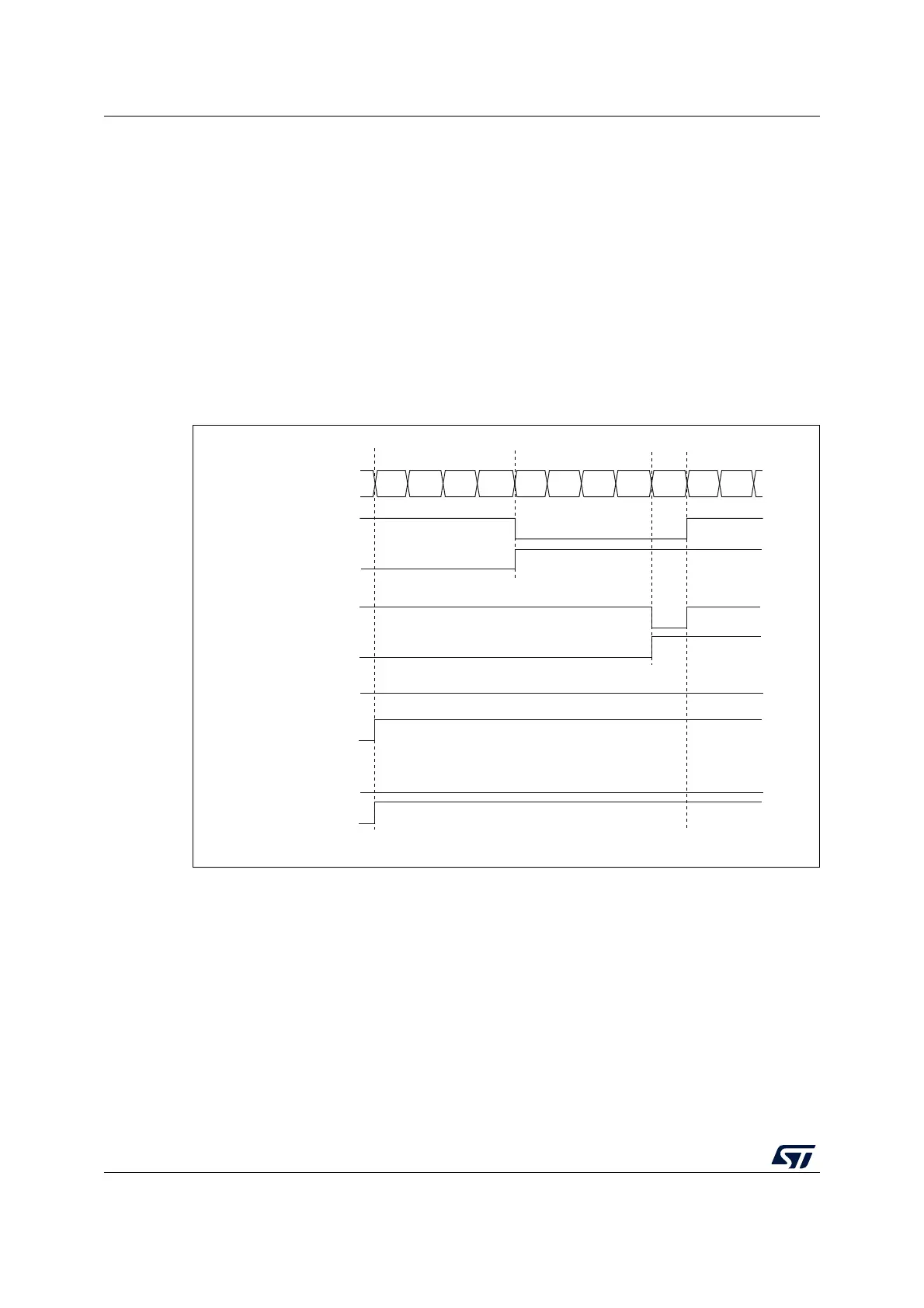
In the following example, we consider PWM mode 1. The reference PWM signal
OCxREF is high as long as TIMx_CNT < TIMx_CCRx else it becomes low. If the
compare value in TIMx_CCRx is greater than the auto-reload value (in TIMx_ARR)
then OCxREF is held at ‘1’. If the compare value is 0 then OCxRef is held at ‘0’.
Figure 181 shows some edge-aligned PWM waveforms in an example where
TIMx_ARR=8.
For code example, refer to A.11.8: Edge-aligned PWM configuration example.
Figure 181. Edge-aligned PWM waveforms (ARR=8)
• Downcounting configuration
Downcounting is active when DIR bit in TIMx_CR1 register is high. Refer to the
Downcounting mode on page 555
In PWM mode 1, the reference signal OCxRef is low as long as
TIMx_CNT > TIMx_CCRx else it becomes high. If the compare value in TIMx_CCRx is
greater than the auto-reload value in TIMx_ARR, then OCxREF is held at ‘1’. 0% PWM
is not possible in this mode.
MS31093V1
Counter register
‘1’
0
12 3456 7801
OCXREF
CCxIF
OCXREF
CCxIF
OCXREF
CCxIF
OCXREF
CCxIF
CCRx=4
CCRx=8
CCRx>8
CCRx=0
‘0’
 Loading...


