RM0367 Rev 7 853/1043
RM0367 Low-power universal asynchronous receiver transmitter (LPUART)
872
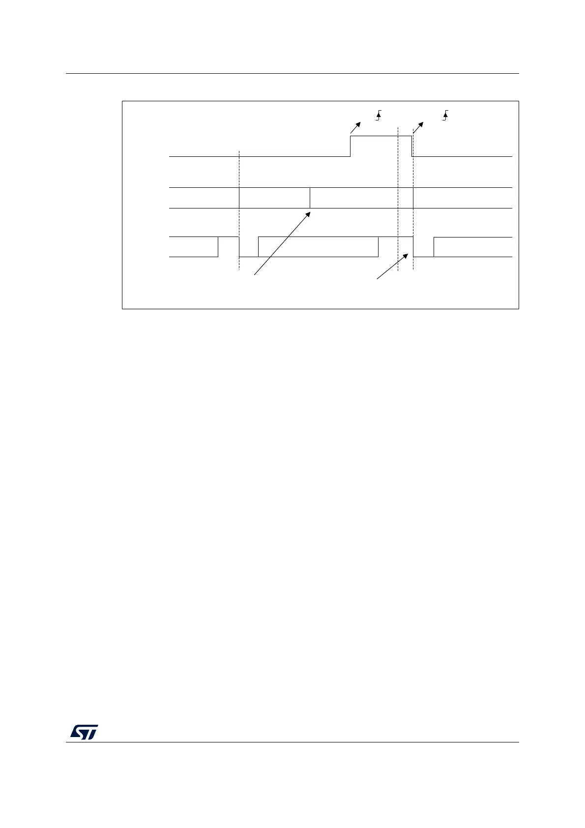
Figure 277. RS232 CTS flow control
Note: For correct behavior, CTS must be asserted at least 3 LPUART clock source periods before
the end of the current character. In addition it should be noted that the CTSCF flag may not
be set for pulses shorter than 2 x PCLK periods.
RS485 Driver Enable
The driver enable feature is enabled by setting bit DEM in the LPUART_CR3 control
register. This allows the user to activate the external transceiver control, through the DE
(Driver Enable) signal. The assertion time is the time between the activation of the DE signal
and the beginning of the START bit. It is programmed using the DEAT [4:0] bit fields in the
LPUART_CR1 control register. The de-assertion time is the time between the end of the last
stop bit, in a transmitted message, and the de-activation of the DE signal. It is programmed
using the DEDT [4:0] bit fields in the LPUART_CR1 control register. The polarity of the DE
signal can be configured using the DEP bit in the LPUART_CR3 control register.
In LPUART, the DEAT and DEDT are expressed in USART clock source (f
CK
) cycles:
• The Driver enable assertion time =
– (1 + (DEAT x P)) x f
CK
, if P <> 0
– (1 + DEAT) x f
CK
, if P = 0
• The Driver enable de-assertion time =
– (1 + (DEDT x P)) x f
CK
, if P <> 0
– (1 + DEDT) x f
CK
, if P = 0
With P = BRR[14:11]
MSv31167V2
Start
bit
Stop
bit
TX
TDR
CTS
Data 1
Data 2
Stop
bit
Idle
Start
bit
Data 2 Data 3
Data 3
empty empty
CTS
CTS
Transmit data register
Writing data 3 in TDR
Transmission of Data 3 is
delayed until CTS = 0