RM0367 Rev 7 833/1043
RM0367 Low-power universal asynchronous receiver transmitter (LPUART)
872
30.4 LPUART functional description
Any LPUART bidirectional communication requires a minimum of two pins: Receive data In
(RX) and Transmit data Out (TX):
• RX: Receive data Input.
This is the serial data input.
• TX: Transmit data Output.
When the transmitter is disabled, the output pin returns to its I/O port configuration.
When the transmitter is enabled and nothing is to be transmitted, the TX pin is at high
level. In Single-wire mode, this I/O is used to transmit and receive the data.
Through these pins, serial data is transmitted and received in normal LPUART mode as
frames comprising:
• An Idle Line prior to transmission or reception
• A start bit
• A data word (7 or 8 or 9 bits) least significant bit first
• 1, 2 stop bits indicating that the frame is complete
• The LPUART interface uses a baud rate generator
• A status register (LPUART_ISR)
• Receive and transmit data registers (LPUART_RDR, LPUART_TDR)
• A baud rate register (LPUART_BRR)
Refer to Section 30.7: LPUART registers for the definitions of each bit.
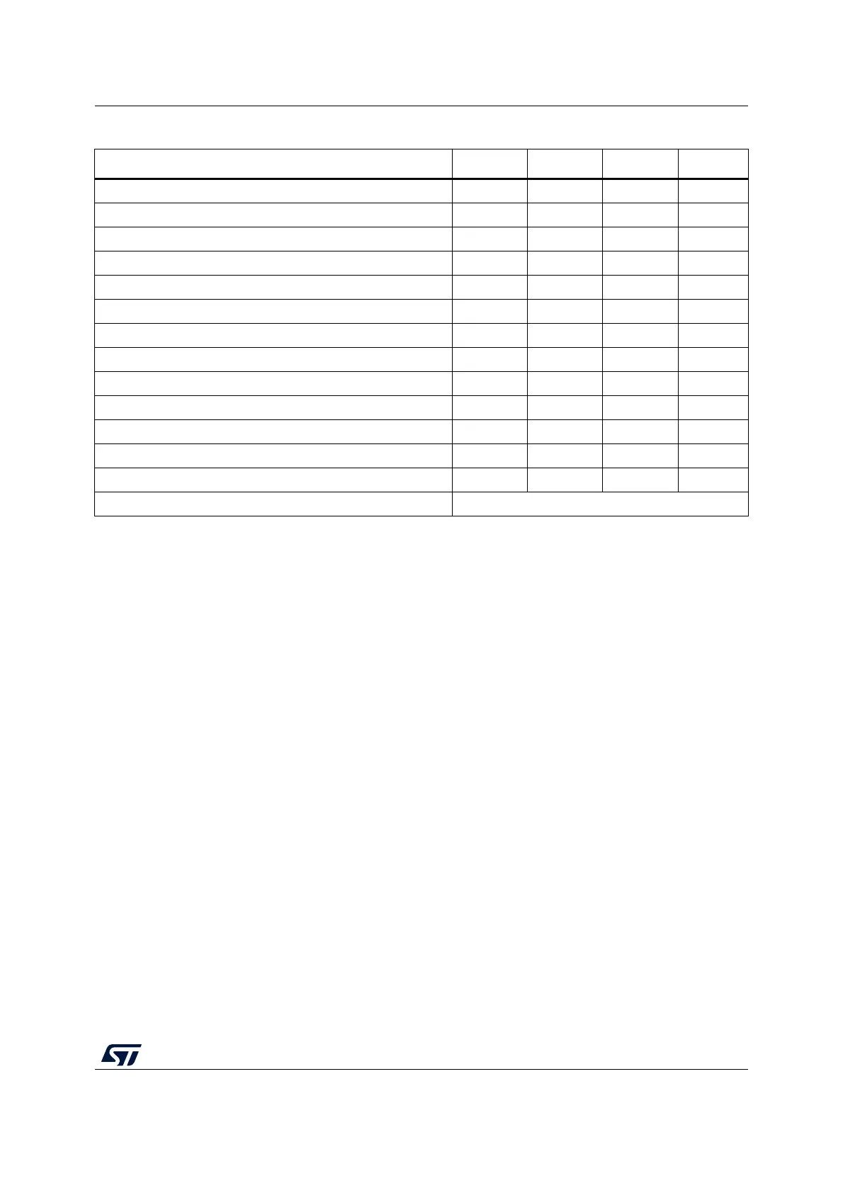
Table 148. STM32L0x3 USART/LPUART features
(1)
USART modes/features USART1/2 USART4 USART5 LPUART1
Hardware flow control for modem X X - X
Continuous communication using DMA X X X X
Multiprocessor communication X X X X
Synchronous mode X X X -
Smartcard mode X - - -
Single-wire Half-duplex communication X X X X
Ir SIR ENDEC block X - - -
LIN mode X - - -
Dual clock domain and wakeup from Stop mode X - - X
Receiver timeout interrupt X - - -
Modbus communication X - - -
Auto baud rate detection X - - -
Driver Enable X X X X
USART/LPUART data length 7
(2)
, 8 and 9 bits
1. X = supported.
2. In 7-bit data length mode, Smartcard mode, LIN master mode and Auto baud rate (0x7F and 0x55 frames) detection are not
supported.
 Loading...


