Digital-to-analog converter (DAC) RM0367
358/1043 RM0367 Rev 7
15.6 Dual-mode functional description
15.6.1 DAC data format
In Dual DAC channel mode, there are three possibilities:
• 8-bit right alignment: data for DAC channel1 to be loaded in the DAC_DHR8RD [7:0]
bits (stored in the DHR1[11:4] bits) and data for DAC channel2 to be loaded in the
DAC_DHR8RD [15:8] bits (stored in the DHR2[11:4] bits)
• 12-bit left alignment: data for DAC channel1 to be loaded into the DAC_DHR12LD
[15:4] bits (stored into the DHR1[11:0] bits) and data for DAC channel2 to be loaded
into the DAC_DHR12LD [31:20] bits (stored in the DHR2[11:0] bits)
• 12-bit right alignment: data for DAC channel1 to be loaded into the DAC_DHR12RD
[11:0] bits (stored in the DHR1[11:0] bits) and data for DAC channel2 to be loaded into
the DAC_DHR12LD [27:16] bits (stored in the DHR2[11:0] bits)
Depending on the loaded DAC_DHRyyyD register, the data written by the user is shifted
and stored in DHR1 and DHR2 (data holding registers, which are internal non-memory-
mapped registers). The DHR1 and DHR2 registers are then loaded into the DOR1 and
DOR2 registers, respectively, either automatically, by software trigger or by an external
event trigger.
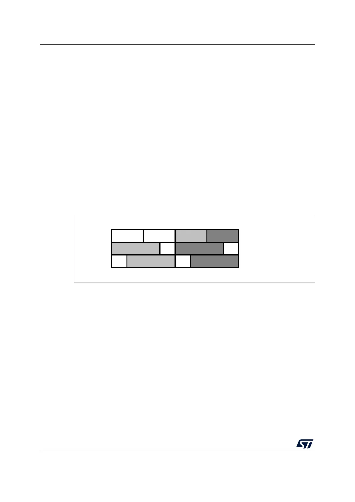
Figure 61. Data registers in dual DAC channel mode
15.6.2 DAC channel conversion in dual mode
The DAC channel conversion in dual mode is performed in the same way as in single mode
(refer to Section 15.5.2) except that the data have to be loaded by writing to DAC_DHR8Rx,
DAC_DHR12Lx, DAC_DHR12Rx, DAC_DHR8RD, DAC_DHR12LD or DAC_DHR12RD.
15.6.3 Description of dual conversion modes
To efficiently use the bus bandwidth in applications that require the two DAC channels at the
same time, three dual registers are implemented: DHR8RD, DHR12RD and DHR12LD. A
unique register access is then required to drive both DAC channels at the same time.
Eleven conversion modes are possible using the two DAC channels and these dual
registers. All the conversion modes can nevertheless be obtained using separate DHRx
registers if needed.
All modes are described in the paragraphs below.
Refer to Section 15.5.2: DAC channel conversion for details on the APB bus (APB or APB1)
that clocks the DAC conversions.
31 24 15 7 0
8-bit right aligned
12-bit left aligned
12-bit right aligned
ai14709b