RM0367 Rev 7 417/1043
RM0367 Touch sensing controller (TSC)
432
Note: Gx_IOy where x is the analog I/O group number and y the GPIO number within the selected
group.
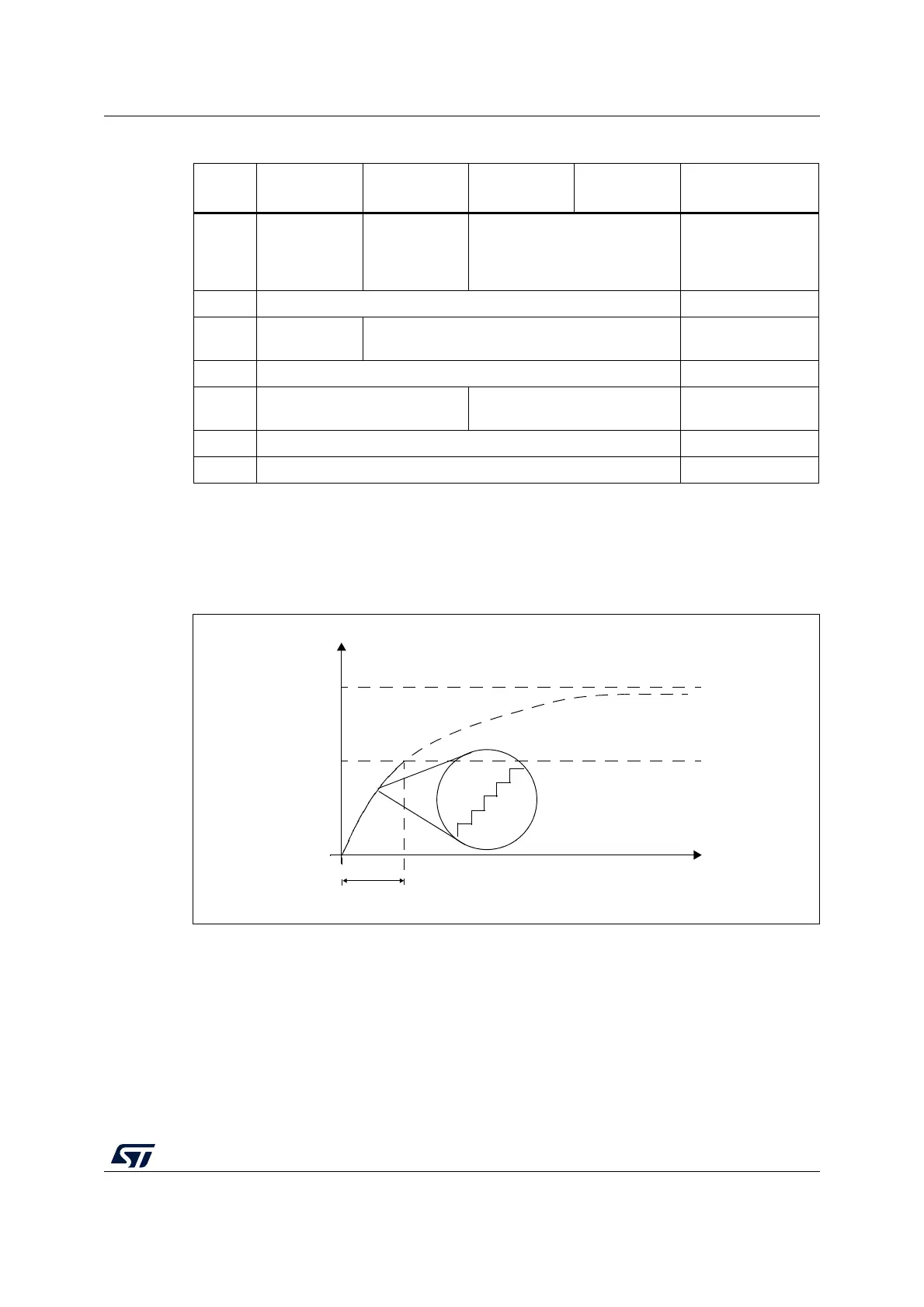
The voltage variation over the time on the sampling capacitor C
S
is detailed below:
Figure 81. Sampling capacitor voltage variation
18.3.3 Reset and clocks
The TSC clock source is the AHB clock (HCLK). Two programmable prescalers are used to
generate the pulse generator and the spread spectrum internal clocks:
• The pulse generator clock (PGCLK) is defined using the PGPSC[2:0] bits of the
TSC_CR register
• The spread spectrum clock (SSCLK) is defined using the SSPSC bit of the TSC_CR
register
Table 81. Acquisition sequence summary
State
Gx_IO1
(channel)
Gx_IO2
(sampling)
Gx_IO3
(channel)
Gx_IO4
(channel)
State description
#1
Input floating
with analog
switch closed
Output open-
drain low with
analog switch
closed
Input floating with analog switch
closed
Discharge all C
X
and
C
S
#2 Input floating Dead time
#3
Output push-
pull high
Input floating Charge C
X1
#4 Input floating Dead time
#5
Input floating with analog switch
closed
Input floating
Charge transfer from
C
X1
to C
S
#6 Input floating Dead time
#7 Input floating Measure C
S
voltage
MS30931V1
t
V
CS
Threshold =V
IH
V
DD
Burst duration